Journal of Fluid Flow, Heat and Mass Transfer (JFFHMT)
ISSN: 2368-6111

Volume 8 - Year 2021 - Pages 100-111
DOI: 10.11159/jffhmt.2021.012
Comparison of Fluid Flow and Thermal Characteristics of Sequential and Simultaneous Crossflow Heat Exchangers
Mohammed Ismail1, Mesbah G. Khan2, Amir Fartaj1
1University of Windsor
401 Sunset Avenue, Windsor, Ontario, Canada
ismailf@uwindsor.ca; fartaj@uwindsor.ca
2Sanden International (U.S.A.) Inc.
47772 Halyard Drive, Plymouth, MI, U.S.A.
khan13j@uwindsor.ca
Abstract - In current research, forced convective heat transfer performance of sequential and simultaneous heat exchanger modules are numerically investigated. The both modules of heat exchangers are identical in height, frontal area, and volume. The simulations have been conducted on serpentine finned heat exchangers in air-to-liquid crossflow orientation. ANSYS FLUENT, a widely used finite volume method based commercial code has been used in the numerical simulations. The heat transfer is concurrently obtained for single phase automatic transmission fluid (ATF) and 50-50 ethylene glycol-water mixture (EG). In liquid-side, the inlet temperature of ATF and EG have been kept constant at 150⁰C and 105⁰C respectively. For both the sequential and the simultaneous orientations, ATF and EG at various mass flow rates within a laminar flow regime have been cooled by air with inlet constant temperature of 25⁰C and velocity of 6.3 m/s. Heat transfer and flow parameters, including approach temperature, heat transfer rate, heat transfer coefficient, effectiveness, and pressure drop have been predicted for the both heat exchanger modules. For a given Reynolds number, simultaneous module predicts significant enhancement of heat transfer rate as well as heat transfer coefficient than that of the conventional sequential module. The liquid-side pressure drop in simultaneous module is predicted significantly higher than that of the sequential module which necessitates a more powerful pump for potential applications. However, difference in the airside pressure drop between the two modules is predicted to be insignificant.
Keywords: Automatic transmission fluid, air-to-liquid crossflow, glycol-water mixture, laminar flow, heat transfer, numerical, sequential, simultaneous.
© Copyright 2021 Authors - This is an Open Access article published under the Creative Commons Attribution License terms Creative Commons Attribution License terms. Unrestricted use, distribution, and reproduction in any medium are permitted, provided the original work is properly cited.
Date Received: 2020-11-13
Date Accepted: 2020-12-18
Date Published: 2021-02-19
Nomenclature
1. Introduction
Heat exchanger plays a vital role in both cooling and heating processes in domestic, commercial, transportation and industrial applications. It is used in air-conditioning, refrigeration, automotive industry, process industry, petrochemical plants, power plant, nuclear reactor, and chemical reactors. Energy demands in every sector have been increasing progressively, while the energy sources are limited [1]. For that reason, it is the paramount for many industries to develop such a heat exchanger that can deliver higher heat transfer. Over the years, many studies [2], [3]–[20] have been done to increase the performance of heat transfer in order to mitigate the increasing energy demands.
With the intention of increasing the heat transfer and improving the heat exchanger performance, the proposed simultaneous approach in crossflow heat exchangers is considered for the automotive applications. In automotive, vehicles need appropriate thermal management systems. Radiator is employed in engine cooling systems, and transmission oil cooler to remove excessive heat from the transmission systems. Vehicles use massive amount of fuels to generate operating power. Vehicle performance is usually evaluated based on fuel consumption and emissions. The strict regulations of emissions set by the Environmental Protection Agency (EPA) [21] can be mitigated by improving efficiency of power train and thermal performance of heat exchangers in HVAC and engine cooling systems. The transmission oil cooler is generally sited in front of the radiator in a conventional sequential arrangement. In this pattern, transmission oil cooler releases heat to the ambient air, which gets warmer before entering the radiator. As a result, the heat transfer performance of the radiator becomes lower compared to the condition when the radiator receives fresh ambient ram air. The heat transfer performance of the radiator can be enhanced by transforming the orientation of the heat exchangers.
In this current research, the transmission oil cooler and the radiator are proposed to place in a simultaneous orientation, where both heat exchangers will receive identical ram or incoming air with the similar ambient conditions. The proposed simultaneous heat exchanger module can significantly minimize the operational energy requirements in automotive applications. It can also improve life cycle climate performance (LCCP) and fulfil the strict emission regulations established by the EPA
2. Numerical Methodology
Numerical simulations of the 3D heat transfer have been conducted through air-to-liquid crossflow heat exchangers using ANSYS Fluent, a widely used finite volume method (FVM) commercial software. Details are illustrated below.
2.1. Computational Domains
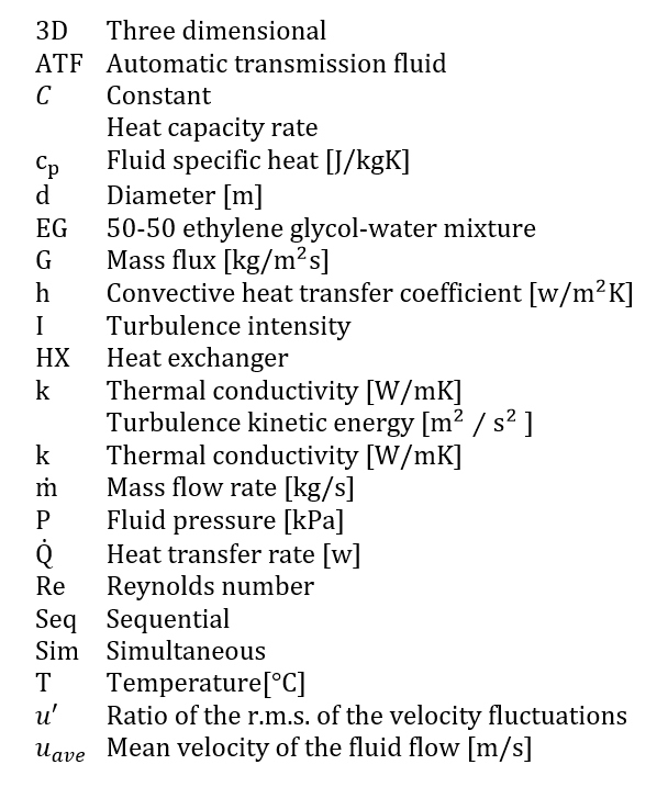
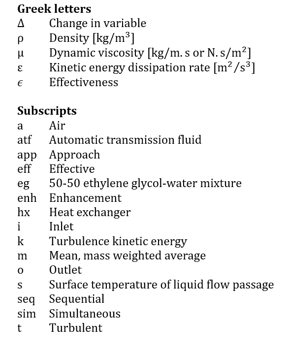
In this study, Gambit 2.4.6 has been used to form the 3D models and computational domains of the conventional sequential and proposed simultaneous heat exchanger (HX) modules. These are presented in Figure 1(a) to Figure 1(d). The specifications of the HX modules are illustrated in Table 1. The both modules are identical in height, width, and length as well as frontal area and volume. Each domain includes three continuums, including ATF, EG and air. Liquid (ATF and EG) and air are separated by solid walls to prevent mixing or direct contact. The airside has been selected in consideration of the test chamber equipped in the experimental setup.
 (a) 3D model of sequential heat exchanger module
 (b) Computational domain of crossflow sequential heat exchanger module
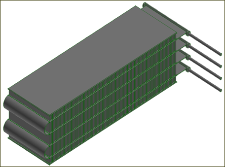 (c) 3D model of simultaneous heat exchanger module
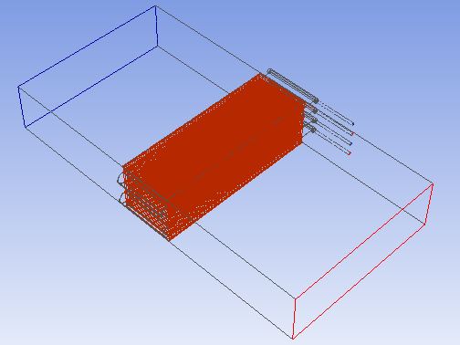 (d) Computational domain of crossflow simultaneous heat exchanger module
Table 1: Specifications of the heat exchanger modules.
| Parameters | Sequential HX | Simultaneous HX |
| Tube height | 1 mm | 1 mm |
| Gap between HXs | 24 mm | - |
| Slab width, x | 38 mm x 2 | 100 mm |
| Slab thickness, y | 2 mm | 2 mm |
| Slab length, z | 305 mm | 305 mm |
| Module height | 92 mm | 92 mm |
| No. of loops | 4 | 2 |
| Slabs in each loop | 2 | 2 |
| Fin density | 12 per 25.4mm | 12 per 25.4mm |
| Fin height | 16 mm | 16 mm |
| Fin thickness | 0.1 mm | 0.1 mm |
| Inlet/exit tube dia. | 4.76 mm | 4.76 mm |
2.2. Mesh Generation
In order to generate meshes for each geometry to be applicable for CFD simulations, Gambit software has been used. The complexity of both flow geometries along with fins led to divide the whole domain into several sub-domains that include air, liquid (pipes, manifolds, serpentines, and tubes), and solid (fins and slabs). Each sub-domain has been discretized with the unstructured (T-Grid, tetrahedral, wedge, etc.) cells. The flow passages adjacent to the walls have been carefully clustered and a grid independency study has been carried out to attain the high-quality CFD result. To check the grid independency, pressure and heat transfer rate profiles have been generated for different cell numbers. Optimal size of cell numbers has been considered for the current study. Approximately, 12.49 × 10⁶ cells for sequential module and 5.78 × 10⁶ for simultaneous module have been used in the CFD simulations. Some grids are illustrated in Figures 2(a) and 2(b).
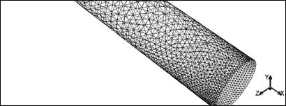 (a) Inlet/outlet pipe mesh (zoomed)
 (b) Air mesh (zoomed)
2.3. Assumptions
In the current study, following key assumptions have been considered for the flow geometry and boundary conditions.
- Fluids are single phase incompressible
- Thermophysical properties of ATF and EG change with temperature; but air and aluminum are constant
- Walls are adiabatic; there is no heat loss or gain to or from the surroundings
- There is no radiation heat transfer in the system
2.4. Flow Regime
Both, the laminar and the turbulent flow have been observed in the different sections of the computational domain. The flow of ATF and EG in the flat tubes are laminar; however, the flow of air in the test chamber as well as ATF and EG in the inlet and outlet pipes are turbulent. For instance, Reynolds numbers (Re) of working fluids at the HX core are 30 ≤ Reatf,core ≤ 250, 225 ≤ Reeg,core ≤ 1900, and Rea,core =6.8× 10⁴. At the inlet boundary, Re are 300 ≤ Reatf ≤ 4165; 2375 ≤ Re eg ≤ 3.3 × 10⁴, and Rea,i = 6.1 × 10⁴ .
2.5. Governing Equations
Based on the key assumptions, the following governing equations have been solved by using ANSYS FLUENT [22].
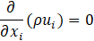
2.5.1. Continuity or mass conservation:
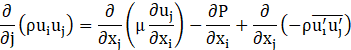
2.5.2. Momentum conservation:
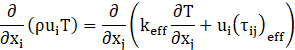
2.5.3. Energy conservation:
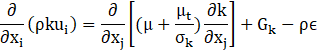
2.5.4. Turbulence kinetic energy, k:
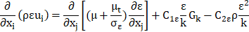
2.5.5. Turbulence energy dissipation, ε:
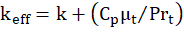
where, Effective thermal conductivity,
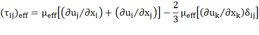
Deviatoric stress tensor,
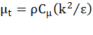
Turbulent viscosity,
Term,

C1ε,C2ε, C3ε, and Cμare constants.
2.6. Computational Setup
Model: A three-dimensional double precision pressure-based velocity coupling steady state solver has been used in the current study. Realizable k-ɛ turbulence model with enhanced wall treatment has been used to capture the turbulence parameters in thermal and flow fields developed around the air-to-liquid crossflow heat exchanger.
Properties of fluids: The thermophysical properties of ATF and EG have been considered temperature dependent. These have been taken from SAE Technical Paper 902148 [23], Anton-Paar Instruments [24], Fluid Properties Calculator [25], and CAN-AM Instruments Ltd. [26].
Solution methods: SIMPLE algorithm has been used with the spatial discretization of Least Square Cell Based gradient, Standard Pressure, and Second Order Upwind energy schemes.
Residuals: The consecutive iteration has been stopped when the normalized absolute residuals in each control volume for the flow and the energy variables have been reduced to and , respectively.
Turbulence intensity: The turbulence intensity (I) has been calculated as [27]

where u', uave, and Redh denote the ratio of the root-mean-square of the velocity fluctuations, the mean velocity of fluid flow, and the Reynolds number of fluid based on hydraulic diameter (dh ), respectively.
2.7. Boundary conditions
Following boundary conditions have been applied in the current study:
- Inlet ATF and EG: mass flow rates and temperature
- Inlet air: velocity and temperature
- Outlet ATF, EG, and air: Pressure outlet
- Walls: No slip, stationary, and adiabatic
2.8. Evaluation of Heat Transfer Parameters
2.8.1. Approach temperature
( Tapp): The approach temperature for the single-phase fluids in a counterflow exchanger is the smallest temperature difference between the hot fluid and the cold fluid. For all other exchangers with single-pass and multipass flow arrangements is the difference between outlet temperatures of hot and cold fluids [28]. In order to ensure good radiator performance, the exit approach temperature between the air and coolant should not be less than 100C. If it is much less than this, it indicates that the radiator is “oversized” for the stated condition or the flow path is too long [29].
In current study, the approach temperature for the single-phase multipass crossflow heat exchanger is evaluated by
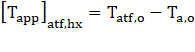
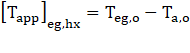
where the subscripts hx, atf, eg, a, and o denote heat exchanger, automatic transmission fluid, 50-50 ethylene glycol-water, air, and outlet temperature, respectively.
2.8.2. Heat transfer rate
(![]() ): The steady state heat transfer rate for all fluids
are calculated as follow.
): The steady state heat transfer rate for all fluids
are calculated as follow.

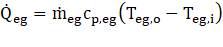
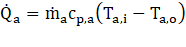
where ![]() = mass flow rate, cp= fluid specific heat, and the subscript i = inlet.
= mass flow rate, cp= fluid specific heat, and the subscript i = inlet.
2.8.3. Enhancement of heat transfer rate (![]() ):
):
The enhancement of heat transfer rate in the proposed simultaneous heat exchanger module is computed as

where the subscripts and represent the simultaneous module and the sequential module, respectively.
2.8.4. Heat transfer coefficient (h ):
The liquid-side heat transfer coefficient is estimated as follow.
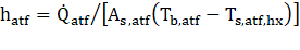

where As = heat transfer surface area, Tb = fluid bulk temperature, and Ts = surface temperature of the liquid flow passage in individual heat exchanger.
2.8.5. Effectiveness (ϵ):
The effectiveness of a heat exchanger is the ratio of the actual heat transfer rate to the maximum possible heat transfer rate [30]. It is computed as below.


where ![]() is the minimum heat capacity rate (
is the minimum heat capacity rate (![]() ) between ATF and air, and
) between ATF and air, and ![]() is the
minimum
is the
minimum ![]() between EG and air
between EG and air
3. Results and Discussions
In this section, the predictions of sequential (Seq) and simultaneous (Sim) heat exchanger (HX) modules are presented. Both modules are identical in slab thickness, height, width, length as well as frontal area and volume. Automatic transmission fluid (ATF) with inlet temperatures of 150℃ and 50-50 ethylene glycol-water mixture (EG) with inlet temperature of 105℃ have been cooled by crossflow air with inlet temperature of 25℃ and velocity of 6.3m/s. The mass fluxes of both liquids have been varied from 130 kg/m2s to 615 kg/m2s . For Seq-HX module, two possible situations have been considered. In Case-I, the EG-HX has been employed in front of the ATF-HX with respect to (w.r.t) the incoming ambient air. While, in Case-II, the ATF-HX has been placed in forward-facing w.r.t the ram air. In Sim-HX module, the ATF-HX has been positioned on the top of the EG-HX. The boundary conditions of each model have been chosen in consideration of the operating conditions of an automotive transmission cooler and radiator when the vehicle runs in the city during the fall.
3.1. Approach Temperature for Seq-HX and Sim-HX Modules for Case-I
The influence of Seq-HX and Sim-HX arrangements on the approach temperature (Tapp) has been numerically predicted. The approach temperatures for Case-I where the EG-HX has been placed in front of the ATF-HX in Seq-HX module are shown in Figure 3(a) and Figure 3(b). For both orientations, the Tapp gradually increases with the increase of liquid-side flow rate. It has been found that for both the ATF-HX and the EG-HX, T app is lower for the simultaneous heat exchanger module than the sequential. This point toward the higher temperature drop as well as the higher heat transfer performance of the Sim-HX module.
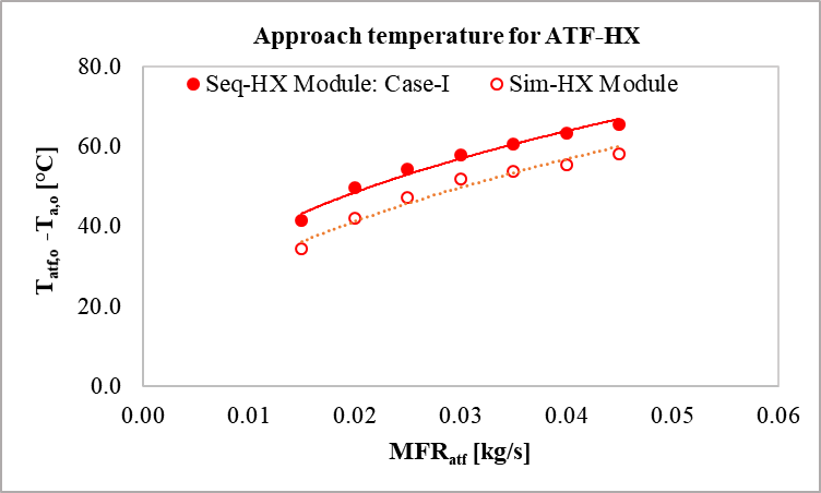 (a) Approach temperature for ATF-HX
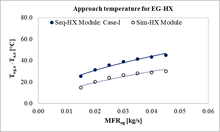 (b) Approach temperature for EG-HX
3.2. Heat Transfer Rate in Seq-HX and Sim-HX Modules for Case-I
In this section, heat transfer rate in Seq-HX and Sim-HX modules for Case-I
are illustrated. The heat transfer rate in ATF-HX and EG-HX are presented
in Figure 4(a) and Figure 4(b), respectively. The heat transfer rate (![]() )
increases with the increase of Reynolds number, as expected. Figure 4(a)
displays about 23% to 25% elevated
)
increases with the increase of Reynolds number, as expected. Figure 4(a)
displays about 23% to 25% elevated ![]() in the ATF-HX in Sim-HX module than that
in the Seq-HX. This is because, the ATF-HX gets the upcoming ambient air in
simultaneous orientation, while it receives the outlet warmer air of EG-HX
in case of sequential. Figure 4(b) shows a little enhanced
in the ATF-HX in Sim-HX module than that
in the Seq-HX. This is because, the ATF-HX gets the upcoming ambient air in
simultaneous orientation, while it receives the outlet warmer air of EG-HX
in case of sequential. Figure 4(b) shows a little enhanced ![]() in simultaneous arrangement at Re ≤ 800 and gradually becomes insignificant or somewhat lower than that of the sequential at Re > 800. It is because, at this point, the outlet ATF temperature supersedes the inlet EG temperature of 105⁰C as shown in Figure 5. Another reason is the thermal interaction between ATF-EX and EG-HX in Sim-HX module. In this module, the inlet slab of EG-HX is connected to the outlet slab of ATF-HX by fins, which exchange heat between the heat exchangers.
in simultaneous arrangement at Re ≤ 800 and gradually becomes insignificant or somewhat lower than that of the sequential at Re > 800. It is because, at this point, the outlet ATF temperature supersedes the inlet EG temperature of 105⁰C as shown in Figure 5. Another reason is the thermal interaction between ATF-EX and EG-HX in Sim-HX module. In this module, the inlet slab of EG-HX is connected to the outlet slab of ATF-HX by fins, which exchange heat between the heat exchangers.
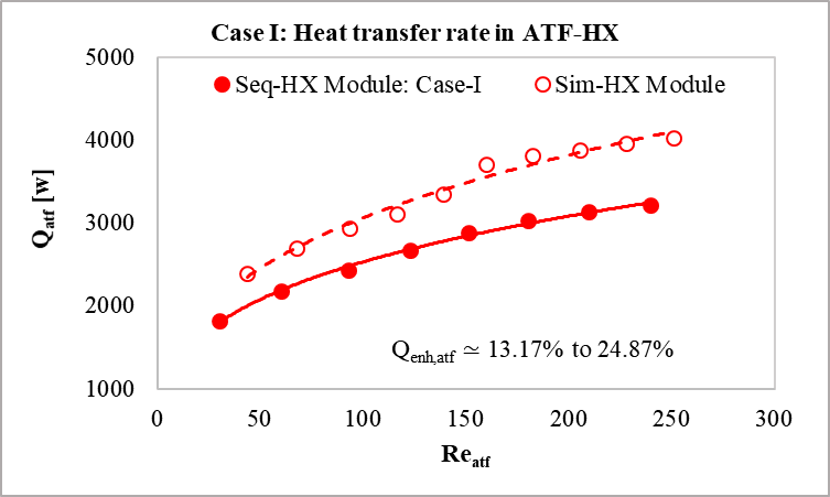 (a) Heat transfer rate of ATF-HX
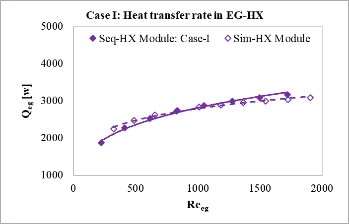 (b) Heat transfer rate of ATF-HX
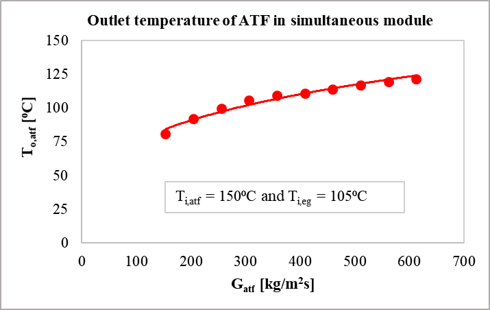
Total heat transfer rate in Seq-HX and Sim-HX modules are illustrated in Figure 6(a). Numerical prediction shows that at a given Reynolds number, the overall heat transfer performance of Sim-HX module is better than that of the conventional Seq-HX. The total heat transfer rate in Sim-HX is found about 10% to 18% higher than that of the Seq-HX as shown in Figure 6(b).
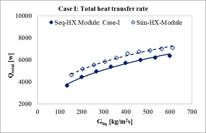 (a) Total heat transfer rate
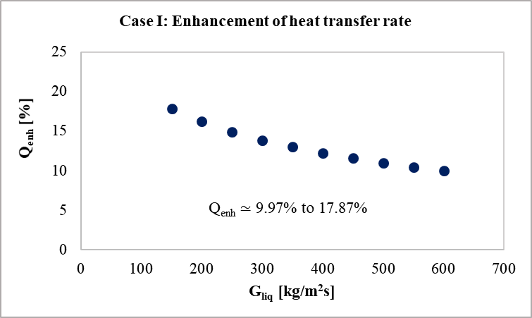 (b) Heat transfer enhancement
3.3. Approach Temperature for Seq-HX and Sim-HX Modules for Case-II
The approach temperature (Tapp) for Case-II are shown in Figure 7(a) and Figure 7(b). Unlike Case-I, the ATF-HX has been placed in front of the EG-HX in Seq-HX module. For both the Seq-HX and the Sim-HX module, the Tapp gradually increases with the increase of liquid-side flow rate. For ATF-HX, particularly at lower flow rate, the variations in Tapp for the Seq-HX and the Sim-HX modules has been found insignificant. Furthermore, the Tapp has been found lower for the simultaneous heat exchanger module than the sequential for both the ATF-HX and the EG-HX. This enhances the heat transfer performance of the Sim-HX module.
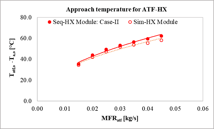 (a) Approach temperature for ATF-HX
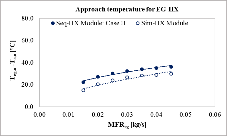 (b) Approach temperature for EG-HX
3.4. Heat Transfer Rate in Seq-HX and Sim-HX Modules for Case-II
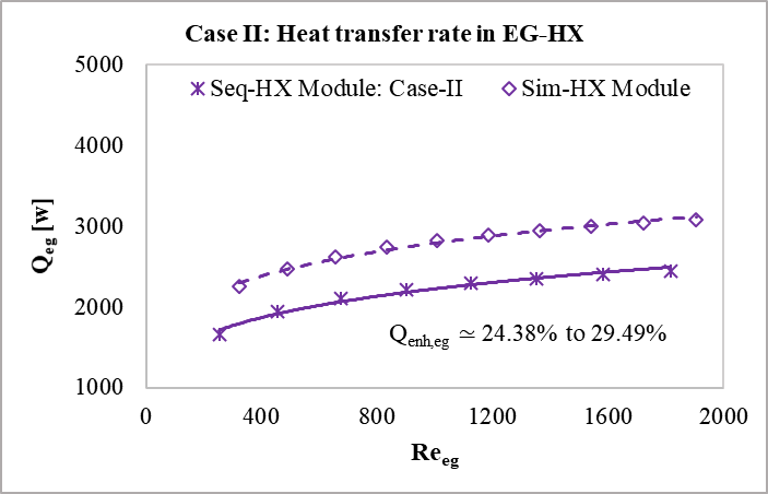
Heat transfer rate in Seq-HX and Sim-HX modules for Case-II are presented in this section. Figure 8(a) illustrates the heat transfer rate of EG-HX which has been placed behind the ATF-HX w.r.t the incoming ambient air. The figure shows significant improvement of heat transfer rate in simultaneous module than the sequential orientation. The enhancement of heat transfer rate in simultaneous arrangement is predicted to be about 24% to 29% compared to the conventional sequential one. This is because, in simultaneous situation, the EX-HX gets the fresh incoming ambient air, while it receives warmer outgoing air of the ATF-HX in case of sequential arrangement.
Figure 8(b) represents the heat transfer rate of ATF-HX which has been placed in front of the EG-HX w.r.t the incoming ambient cold air. As expected, the heat transfer rate increases with increase of Reynolds number. About 7% to 12% enhancement in heat transfer rate of the ATF-HX has been observed in simultaneous orientation than the conventional sequential arrangement. This is because, both the ATF-HX and EG-HX get the incoming ambient air in simultaneous arrangement, while the EG-HX receives delivery of the outlet warmer air of the ATF-HX in sequential module. There is also thermal interaction between ATF-EX and EG-HX in simultaneous arrangement. The inlet slab of EG-HX and the outlet slab of ATF-HX are connected by fins and transfer heat by means of thermal interaction.
 (a) Heat transfer rate in EG-HX
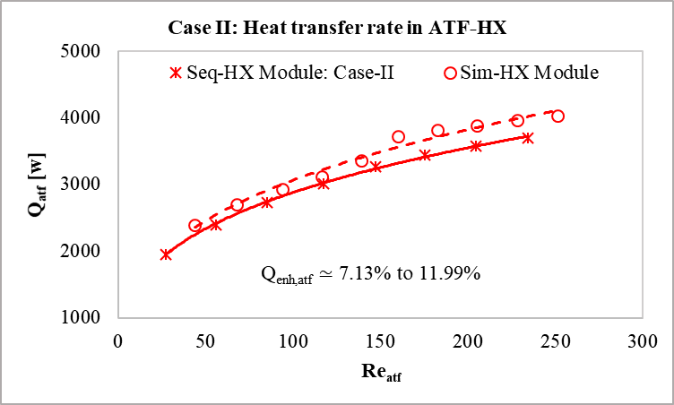 (b) Heat transfer rate in EG-HX
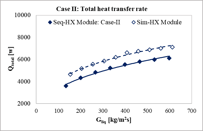
The inlet temperature of EG is 105⁰C for both the simultaneous and the sequential modules. On the other hand, the outlet temperature of ATF temperature varies from 80⁰C to 120⁰C, which has shown earlier in Figure 5. The overall heat transfer rate in simultaneous and sequential heat exchangers are illustrated in Figure 9(a). The total heat transfer rate of simultaneous HX is better than that of the conventional sequential HX. The heat transfer rate in simultaneous HX is found to be about 14% to 20% higher than that of the sequential HX as shown in Figure 9(b).
 (a) Total heat transfer rate
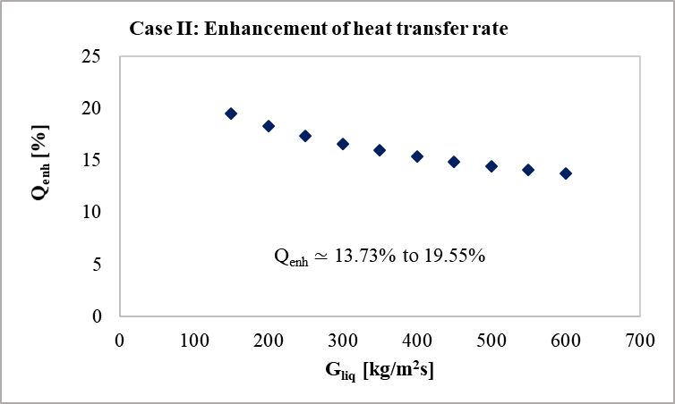 (b) Heat transfer enhancement
3.5 Heat Transfer Coefficient of Liquids in Seq-HX and Sim-HX Modules
The numerical prediction of forced convection heat transfer coefficient (h) of ATF and EG in Seq-HX and Sim-HX modules are shown in Figure 10. For both, the ATF and the EG, it is found that the h increases with the increase of mass flux and follows power law relationship with positive exponent. The correlations for the mass flux of 133 ≤ Gliq ≤ 615 are stated below.


The heat transfer coefficient of ATF in the Sim-HX module is predicted about 11% to 14% higher than that of the Seq-HX module. While it is approximately 4% to 5% higher in case of EG.
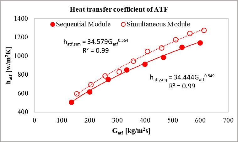 (a) Heat transfer coefficient of ATF
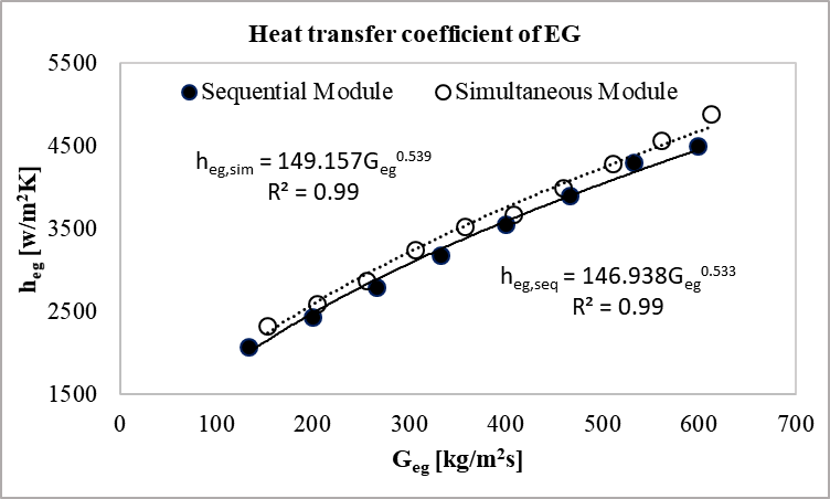 (b) Heat transfer coefficient of EG
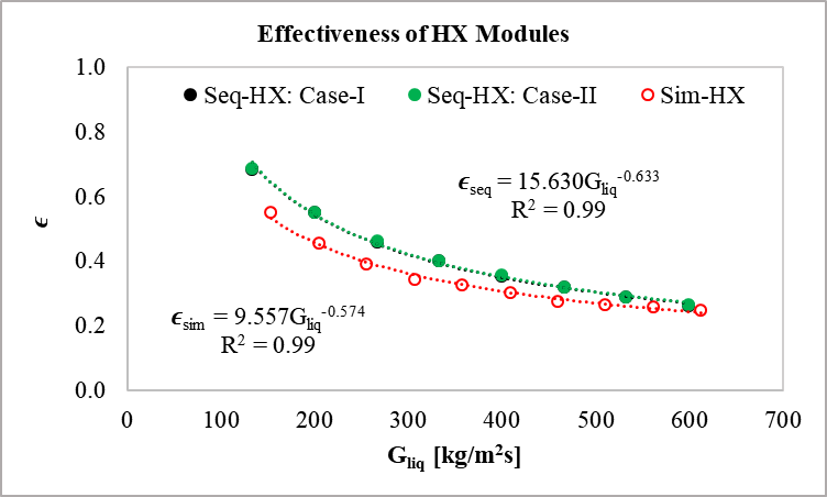
3.6 Effectiveness of Seq-HX and Sim-HX Modules
The effectiveness (ϵ) of the sequential and simultaneous heat exchanger modules are determined using equations (18), (19), and (20). Figure 11 illustrates the comparison of effectiveness of Seq-HX and Sim-HX modules for the mass flux of 133 ≤ Gliq ≤ 615 . It is predicted that the ϵ decreases with the increase of Gliq for both the Seq-HX and the Sim-HX modules. It follows a power law relation with negative exponent. For a given Gliq, the ϵ is found greater for Seq-HX than the Sim-HX module. This is due to the thermal interaction between ATF-HX and EG-HX in case of simultaneous orientation. In this arrangement, the outlet slab of ATF-HX and the inlet slab of EG-HX are connected by fins and exchange heat by means of thermal interaction. The correlations for heat exchanger effectiveness for the mass flux of 133 ≤ Gliq ≤ 615 are given below.


3.7 Pressure Drop in Seq-HX and Sim-HX Modules
Pressure drop (ΔP) is one of the vital factors in the heat exchanger performance. The overall ΔP in the heat exchanger denotes the sum of pressure drop over the flow length throughout the inlet and outlet pipes, manifolds, and serpentines. The overall ΔP of ATF and EG in Seq-HX and Sim-HX modules are illustrated in Figures 12(a) and 12(b).
Numerical results predict significantly higher ΔP in simultaneous arrangement than that of the sequential arrangement. For a specific mass flux, the liquid-side ΔP in Sim-HX module is predicted almost double compared to the Seq-HX module that necessitates a more powerful pump for potential applications.
Airside ΔP in the Seq-HX and Sim-HX modules are reported in Figure 13. The airside ΔP in Sim-HX module is computed about 4.3% to 6.1% lower than that in the Seq-HX module.
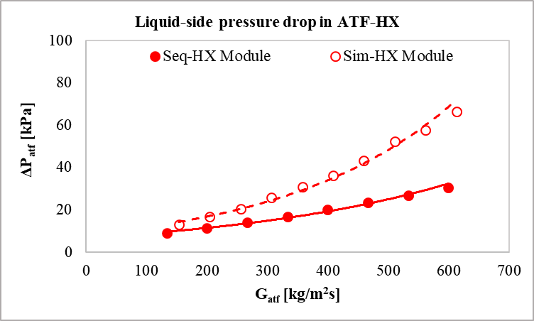 (a) Liquid-side pressure drop in ATF-HX
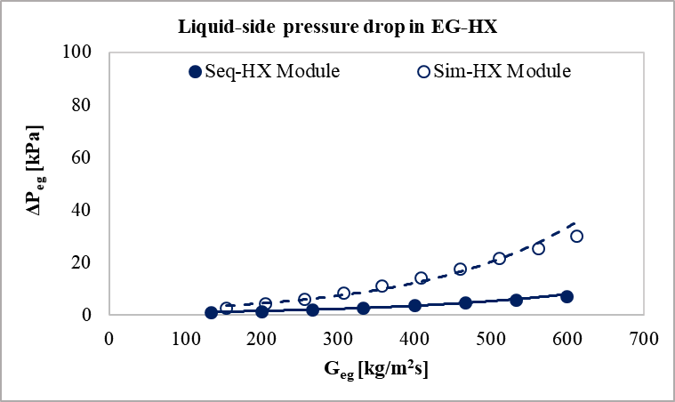 (b) Liquid-side pressure drop in EG-HX
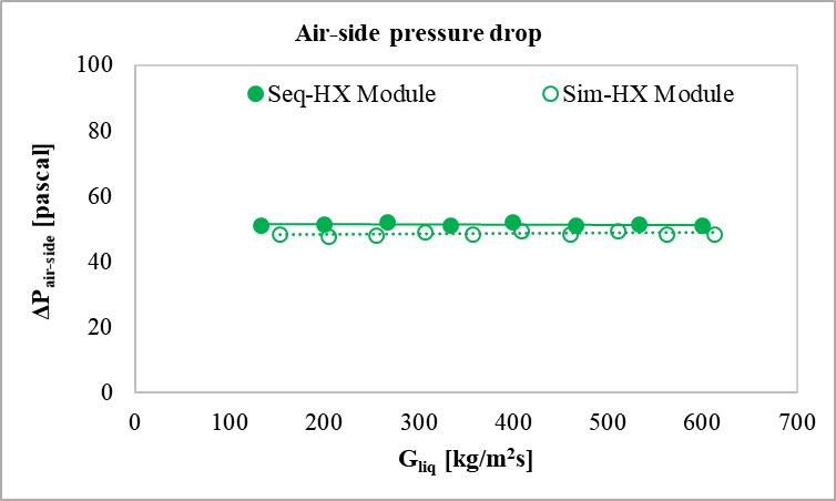
4. Conclusion
The current research has been performed to numerically investigate the heat transfer performance of sequential and simultaneous heat exchanger modules. Single-phase automatic transmission fluid and 50-50 ethylene glycol-water have been cooled by air in a crossflow orientation. Focal thermal and flow parameters, such as approach temperature, heat transfer rate, heat transfer coefficient, effectiveness, pressure drop, Reynolds number, and mass flux are predicted. Following conclusions have been drawn from the research findings:
- Proposed Sim-HX module, where both HXs receive identical incoming cold air with the similar ambient conditions outperforms conventional Seq-HX module. It can significantly improve the heat transfer performance.
- Lower approach temperature has been predicted for Sim-HX module than the Seq-HX, which point toward the higher heat transfer performance of the Sim-HX module.
- The enhancement in heat transfer rate has been predicted about 24% to 29% for EG-HX and 7% to 12% for ATF-HX due to the replacement of sequential arrangement with the simultaneous one. The overall enhancement has been found about 14% to 20%.
- Heat transfer coefficient of ATF in the Sim-HX module has been predicted about 11% to 14% higher that that of the Seq-HX module. While it is approximately 4% to 5% higher in case of EG.
- Higher effectiveness has been predicted in Seq-HX than the Sim-HX module because of thermal interaction between two heat exchangers.
- The liquid-side pressure drop, ΔP in the Sim-HX module has been found about double compared to that in the Seq-HX module. However, the difference in the airside ΔP between two modules is found insignificant.
Acknowledgements
The authors gratefully acknowledge the Natural Sciences and Engineering Research Council of Canada (NSERC) for providing discovery grant (DG) to accomplish the current research. The authors are also thankful to the department of Mechanical Automotive & Materials Engineering at University of Windsor for giving the Postdoctoral research opportunity.
References
[1] M. G. Khan and A. Fartaj, “A review on microchannel heat exchangers and potential applications,” International Journal of Energy Research, vol. 35, pp. 553–582, 2011. View Article
[2] J. Liu, S. Hussain, W. Wang, L. Wang, G. Xie, and B. Sundén, “Heat transfer enhancement and turbulent flow in a rectangular channel using perforated ribs with inclined holes,” Journal of Heat Transfer, vol. 141, pp. 041702, 1–15, 2019. View Article
[3] E. S. Dasgupta, S. Askar, M. Ismail, A. Fartaj, and M. A. Quaiyum, “Air cooling by multiport slabs heat exchanger: An experimental approach,” Experimental Thermal and Fluid Science, vol. 42, pp. 46–54, 2012. View Article
[4] E. S. Dasgupta, F. A. Siddiqui, and A. Fartaj, “Experimental study on air side heat transfer and fluid flow characteristics of microchannel heat exchanger,” SAE International Journal of Materials and Manufacturing, vol. 4, no. 1, pp. 1198–1210, 2012. View Article
[5] M. Ismail, S. Fotowat, and A. Fartaj, “Effect of channel size on heat transfer and pressure drop in thin slabs minichannel heat exchanger,” International Journal of Mechanical Engineering and Mechatronics, vol. 2, no. 1, pp. 32–41, 2014. View Article
[6] A. Jokar, S. J. Eckels, and M. H. Hosni, “Single-phase flow in meso-channel compact heat exchangers for air conditioning applications,” Heat Transfer Engineering, vol. 31, no. 1, pp. 3–16, 2010. View Article
[7] M. S. Saadi, M. Ismail, S. Fotowat, M. A. Quaiyum, and A. Fartaj, “Study of motor oil cooling at low Reynolds number in multi-port narrow channels,” SAE International Journal of Engines, vol. 6, no. 2, pp. 1287–1298, 2013. View Article
[8] M. A. Quaiyum, A. Fartaj, and S. Askar, “An experimental characterization of automatic transmission fluid flowing through air cooled microchannel heat exchanger,” SAE International Journal of Materials and Manufacturing, vol. 5, no. 2, pp. 503–516, 2012. View Article
[9] Y. Fan and L. Luo, “Recent applications of advances in microchannel heat exchangers and multi-scale design optimization,” Heat Transfer Engineering, vol. 29, pp. 461–474, 2008. View Article
[10] N. B. Chien, P. Q. Vu, N. M-Ghazali, and O. J-Taek, “Convective heat transfer characteristics of single phase liquid in multiport minichannel tube: Experiment and CFD simulation,” Energy Procedia, vol. 75, pp. 3180–3185, 2015. View Article
[11] M. E. Steinke and S. G. Kandlikar, “Single-phase heat transfer enhancement techniques in microchannel and minichannel flows,” in The 2nd International Conference on Microchannels and Minichannels , 2004, pp. 1–8. View Article
[12] M. Ismail, M. G. Khan, and A. Fartaj, “Evaluation of Crossflow Heat Exchanger Modules in Sequential and Simultaneous Orientations,” Heat and Mass Transfer Research Journal, vol. 3, no. 2, pp. 1–23, 2019.
[13] M. Ismail, A. Fartaj, and M. Karimi, “Numerical investigation on heat transfer and fluid flow behaviors of viscous fluids in a minichannel heat exchanger,” Numerical Heat Transfer, Part A: Applications, vol. 64, no. 1, pp. 1–29, 2013. View Article
[14] S. Fotowat, A. Fartaj, M. Ismail, M. A. Quaiyum, and S. Askar, “Experimental study on air-heating through a cross-flow minichannel heat exchanger,” CSME International Conference, pp. 1–6, 2012.
[15] M. A. Quaiyum, M. Ismail, and A. Fartaj, “Study of automatic transmission fluid in a serpentine minichannel heat exchanger: An experimental approach,” Experimental Heat Transfer, vol. 28, no. 3, pp. 244–266, 2015. View Article
[16] W. Wang and X. Wang, “Experiments of condensation heat transfer in micro channel heat exchanger,” in International Refrigeration and Air Conditioning Conference at Purdue , 2010, pp. 2290, 1–6.
[17] A. Arteconi, G. Giuliani, M. Tartuferi, and F. Polonara, “Characterization of a mini-channel heat exchanger for a heat pump system,” Journal of Physics: Conference Series, vol. 501, no. 1, pp. 0–10, 2014. View Article
[18] M. Asadi, G. Xie, and B. Sunden, “A review of heat transfer and pressure drop characteristics of single and two-phase microchannels,” International Journal of Heat and Mass Transfer, vol. 79, pp. 34–53, 2014. View Article
[19] Y. Zhai, G. Xia, Z. Li, and H. Wang, “Experimental investigation and empirical correlations of single and laminar convective heat transfer in microchannel heat sinks,” Experimental Thermal and Fluid Science, vol. 83, pp. 207–214, 2017. View Article
[20] Z. Li, W. Q. Tao, and Y. L. He, “A numerical study of laminar convective heat transfer in microchannel with non-circular cross-section,” International Journal of Thermal Science, vol. 45, pp. 1140–1148, 2006. View Article
[21] EPA, “Emission standards reference guide for on-road and nonroad vehicles and engines,” U.S. Environmental Protection Agency. 2016. View Article
[22] ANSYS Inc., ANSYS Fluent Theory Guide, R15 ed. Canonsburg, USA, 2013.
[23] S. P. Kemp and J. L. Linden, “Physical and Chemical Properties of a Typical Automatic Transmission Fluid,” in SAE International in United States, 1990, Technical Paper 902148. View Article
[24] “Viscosity of Automatic Transmission fluid (ATF) – viscosity table and viscosity chart.” View Article
[25] Fluid Properties Calculator, “Microelectronics Heat Transfer Laboratory, University of Waterloo.” View Article
[26] CAN-AM Instruments Ltd., “2851 Brighton Road, Oakville, Ontario, L6H 6C9, Canada.” .
[27] ANSYS Inc., ANSYS Fluent User’ s Guide, R15 ed. Canonsburg, USA, 2013.
[28] R. K. Shah and D. P. Sekulic, Fundamentals of Heat Exchanger Design. Hoboken, New Jersey, U.S.A: John Wiley & Sons, Inc., 2003. View Article
[29] A. Kargilis, Design and Development of Automotive Engine Cooling Systems. Southfield, Michigan, USA, 2005.
[30] T. L. Bergman, A. S. Lavine, F. P. Incorpera, and D. P. Dewitt, Fundamentals of heat and mass transfer, 7th ed. John Wiley & Sons, Inc, USA, 2011.