Journal of Fluid Flow, Heat and Mass Transfer (JFFHMT)
ISSN: 2368-6111

Volume 8 - Year 2021 - Pages 93-99
DOI: 10.11159/jffhmt.2021.011
Influence of Obstacle Shapes in a Tubular Geometry with Two Obstacles of Variable Spacing
Abdulmajid M. Na’inna1, Heredotos N. Phylaktou2, Gordon E. Andrews2
1Nigerian Air Force Institute of Technology, Armament Engineering Department
Mando Road, Kaduna, Nigeria, PMB 2104
abdulmajid.nainna@airforce.mil.ng
2University of Leeds, Energy Research Institute
University of Leeds, Leeds, West Yorkshire, United Kingdom, LS2 9JT
H.N.Phylaktou@leeds.ac.uk
Abstract - Previous studies on the influence of obstacle shapes in gas explosions involved mainly single obstacles whereas only a few studies focused on multi-obstacle with constant spacing between obstacles. This paper is aimed at studying the influence of obstacle spacing on two obstacles of various shapes in a tubular geometry using 10% methane-air mixtures. For single obstacles of 20% blockage, 1-flat-bar produced the highest explosion severity followed by a baffle disc and orifice plate. The reverse was the case for 30% obstacle blockage. In case of double obstacle optimally spaced, 1-flat-bar produced a peak overpressure of 1.29 bar and 2.42 bar for 20% and 30% blockage ratios respectively. Maximum overpressures of 0.81 bar and 2.67 bar were generated for 20% and 30% blockage ratios respectively for double 1-hole obstacles at worst case spacing.
Keywords: Flame acceleration, Gas explosions, Obstacle shape, Obstacle, Obstacle spacing.
© Copyright 2021 Authors - This is an Open Access article published under the Creative Commons Attribution License terms Creative Commons Attribution License terms. Unrestricted use, distribution, and reproduction in any medium are permitted, provided the original work is properly cited.
Date Received: 2019-06-01
Date Accepted: 2019-12-21
Date Published: 2021-02-19
1. Introduction and Literature Survey
Under similar experimental conditions, obstacles of various shapes produce different gas explosion overpressures and hence gas explosion severity. Thin or sharp-edged obstacles generate higher turbulence levels than thick or round edged obstacles. This could be due to the influence of turbulence generation constant, CT and hence higher turbulence intensity in the shear layer produced by a sharp obstacle than that produced by a round obstacle [1]. Experiments from a wedge-shaped vessel showed that the pressure development due to sharp obstacles was nearly doubled of the round obstacles[2] . This corroborated the findings from the experiments where an overpressure factor of 2-3 higher was attained for sharp edged obstacles compared to round ones for low to moderate blockage ratios [3]. However, Phylaktou [4] obtained a factor of 5.5. It was also demonstrated that the influence of obstacle shape on flame speed was more sensitive to low level of congestions than for high level [5]. Other experimental works have studied the influence of gas explosions with obstacles of various shapes [6-16].
The previous studies on the influence of obstacle shapes in gas explosions involved mainly single obstacles[7-10,12-13,16] whereas only a few studies focused on multi-obstacle with constant spacing between obstacles [6,11,14-15]. The spacing between obstacles has been systematically studied recently by Na’inna et al. [17]. The authors found that two obstacles optimally spaced could produce same or higher explosion severity compared to large number of obstacles closely spaced. Further studies on the effects of obstacle separation distance were performed on obstacles of various blockage ratio, scales, numbers and fuel types [18-21].
It was the aim of this paper to study the influence of various obstacle shapes (single-hole, single flat-bar and baffle disc) in a tubular geometry with two obstacles of variable obstacle separation distance. The single-hole (orifice plate) in the current study represented sharp-edged orifice plates situated perpendicular to the approaching flow. At the plane of an orifice opening, flow separates from the surface of the orifice to a form a discrete jet. Subsequently, recirculation zones are formed. Therefore in the current test geometry, the flow was not instantly influenced by the walls of the test vessel immediately downstream of the orifice but was free to develop radially. Equally, gas flow through 1- flat-bar obstacle was directed between the edges of the obstacle and the wall of the test-vessel. Recirculating regions would then initiate behind the bar towards the vessel centreline. The disc baffle could be regarded as flat, sharp-edged plates placed perpendicular to the oncoming flow. The disc had a larger obstacle scale when compared to both single-hole and flat-bar [9].
2. Experiments
A long cylindrical vessel 162 mm internal diameter made from nine flanged sections, 8 of them of 0.5 m length each and one section 0.25m in length (total nominal length of 4.25m) was used as the explosion tube. The test vessel was rated to withstand an overpressure of 35 bar. It was mounted horizontally and closed at the ignition end, with its open end connected to a large cylindrical dump-vessel with a volume of 50 m3. This arrangement enabled the simulation of open-to-atmosphere explosions with accurate control of both test and dump vessels pre-ignition conditions.
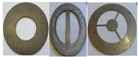
Two obstacles of various shape namely: single-hole, single -flat-bar and baffle disc types as shown in Fig. 1 were used to generate turbulence in the explosion tube. The obstacles were made from stainless steel of 3.2 mm thickness. Two obstacle blockage ratios, BR of 20% and 30% were used in the experiments. The BR is dependent on obstacle scale, b which is the width of the solid material of the obstacle and it differs for the three different obstacle shapes despite having similar BR.
The obstacles were mounted between the section flanges. For all tests, the first obstacle was positioned 1 m downstream of the spark while the second obstacle’s position was varied from 1.25 m to 2.75 m downstream of the first obstacle in order to obtain the worst case obstacle spacing. The range of the obstacle spacing was based on the correlation for the prediction of worst case obstacle separation distance from cold flow turbulence [18]. A pneumatically actuated gate valve isolated the test vessel prior to mixture preparation. A vacuum pump was used to evacuate the test vessel before a 10 % (by vol.) methane-air mixture was formed using partial pressures, to a total mixture pressure of 1 atm. The dump vessel was filled with air to a pressure of 1 atm as well. After mixture circulation, allowing for at least 4 volume changes, the gate valve to the dump vessel was opened and a 16 Joule spark plug ignition was effected at the centre of the test vessel closed-end flange. The test vessel had an overall length-to-diameter ratio, L/D of 27.7. The set-up is shown in Fig. 2.
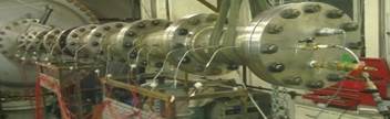
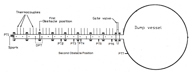
Figure 2. Experimental set-up (a) Photograph (b) Schematic diagram.
An array of 24 type-K mineral insulated exposed junction thermocouples positioned along the axial centre line of the test vessel was used to record the time of flame arrival. Average flame speeds allocated to the midway position between two thermocouples were obtained by dividing the distance between two thermocouples by the difference in time of flame arrival at each thermocouple position. A smoothing algorithm was applied to the flame arrival data, as described by Gardner [9], to avoid either high or negative flame speeds where the flame brush appears to arrive at downstream centreline locations earlier than upstream ones, particularly in the regions of strong acceleration downstream of the obstacles. This method of smoothing over the consecutive thermocouple positions was reiterated until the maximum resulting flame speed was +/- 10% of the maximum calculated from the previous smoothed flame position data series. The test vessel and dump vessel pressure histories were recorded using an array of 8 Keller-type pressure transducers - 7 gauge pressure transducers (PT1 to PT7) and 1 differential (DPT), as shown in Fig. 2. Wall static pressure tapping measured by a differential pressure transducer (DPT) were located at 1D upstream and 0.5D downstream of the first obstacle as specified by British Standards [22]. Pressure transducers, PT3 and PT4 were positioned 1D upstream and 0.5D downstream of the second obstacle and they were used to obtain the pressure differential across these obstacles. The pressure drops across such obstacles were used in calculating the induced gas flow velocities, Sg and other flow turbulence characteristics [23]. Pressure transducers PT1 and PT6 were positioned permanently at the ignition position-end flange and end of the test vessel (25D from the spark) respectively. The pressure history in the dump vessel was measured using PT7 positioned as shown in Fig 2.
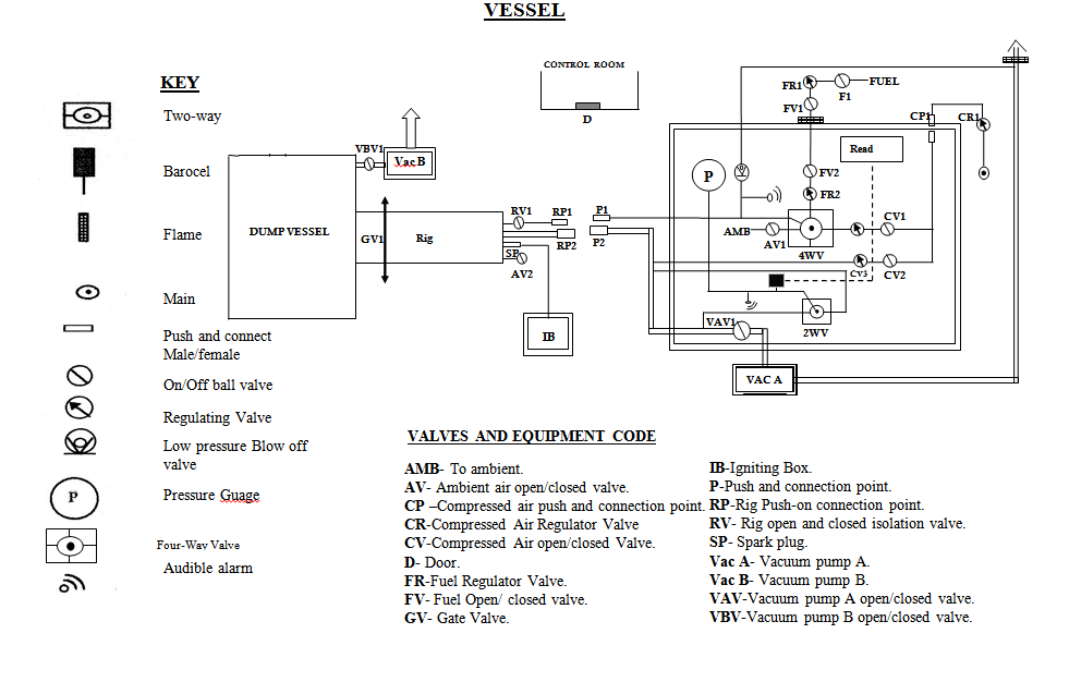
A 32-channel (maximum sampling frequency of 200 KHz per channel) transient data recorder (Data Logger and FAMOS) was used to record and process the explosion data. Figure 3 shows a schematic diagram of the complete experimental set in the explosion laboratory.
Each test was repeated at least three times. For clarity purposes, average results are shown for the analysis of flame speed, Sf and overpressure, P. In total, over 54 tests were carried out demonstrating 18 different test conditions. Table 1 shows a list of the tests carried out as part of this work and an overview of the results.
Table 1. Summary of tests conditions and results.

3. Results and Discussions
3. 1. Single obstacles
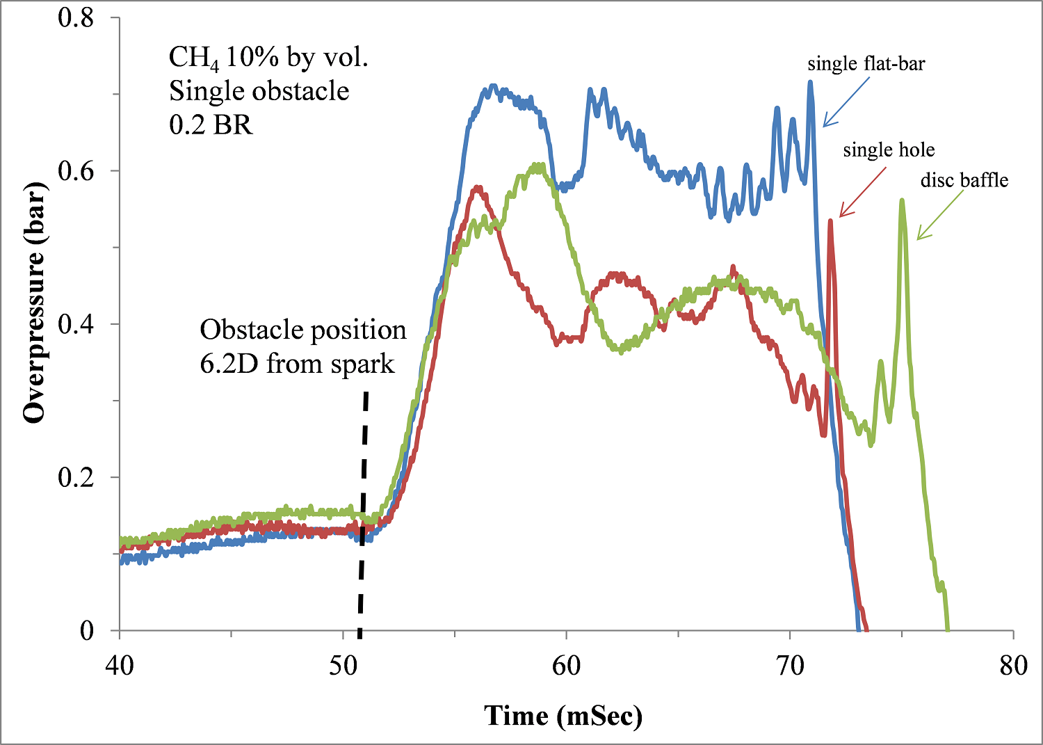
Figure 4 shows an overpressure-time profile for single obstacles of various shapes (single-hole, single flat-bar and baffle disc) of 20% BR each. Upon the ignition of the flammable mixtures at xig/D = 0, the flame propagates at relatively similar overpressure of about 0.1 bar for the three configuration of the obstacles. The propagating flame approaches an obstacle positioned at 6.2D from the spark at about 51 mSec. Downstream of the obstacle, there was sharp rise in overpressure of about 0.67 bar, 0.60 bar and 0.57 bar for single-flat bar, baffle disc and single-hole obstacles respectively at about 55 mSec each for the grid plate obstacles and 58 mSec for the baffle disc. The longer duration for the disc baffle shows a slower flame propagation compared to the grid plate obstacles (single-flat bar and single-hole). Subsequently, strong pressure oscillations for the three types of obstacles were encountered until the flame exited the explosion tube at about 73 mSec and 77 mSec for the grid plate and baffle disc obstacles respectively.
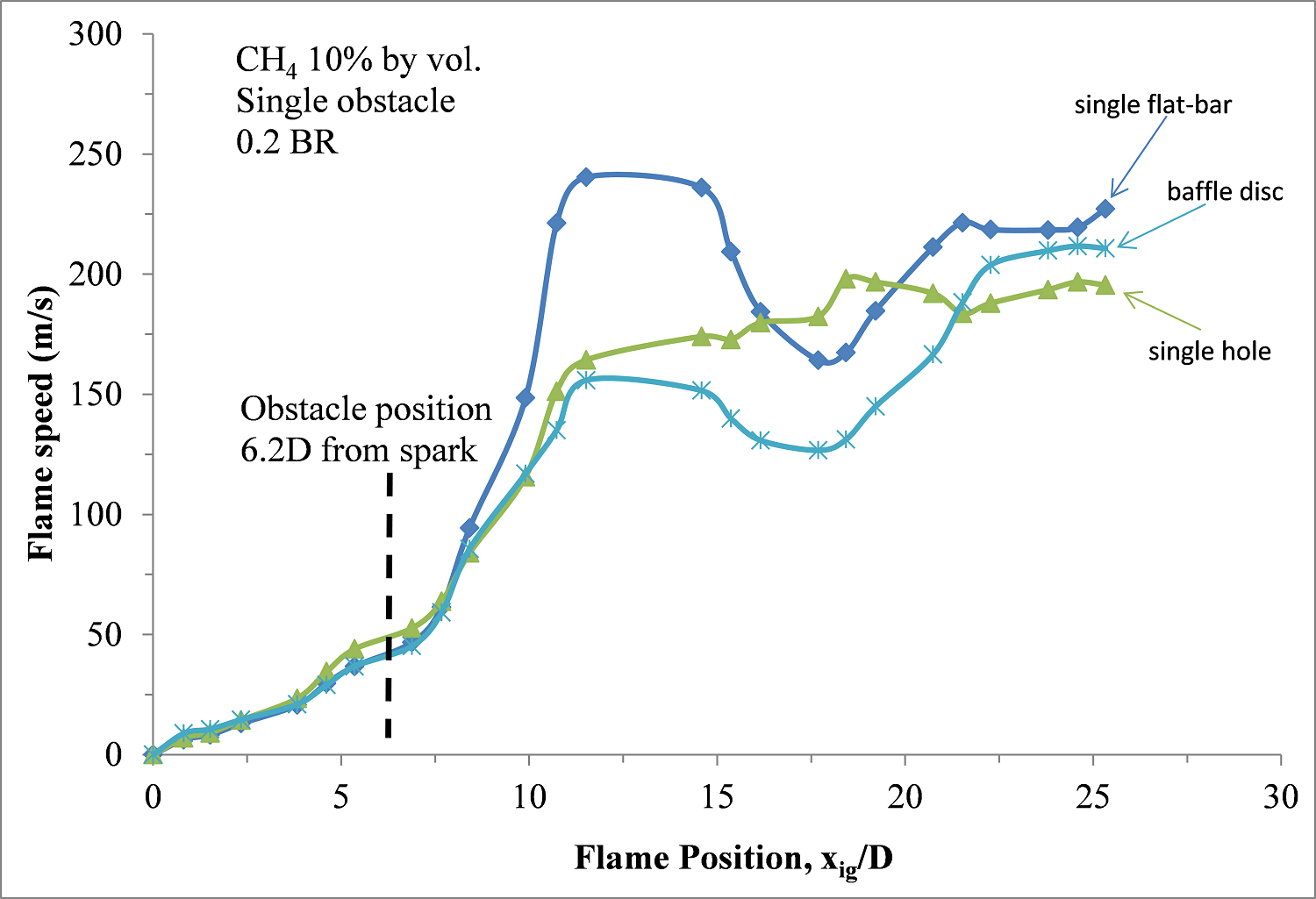
A flame speed propagation as a function of dimensionless flame position (xig/D) for the three different obstacle shapes is shown in Fig. 5. Prior to the arrival of the propagating flame to an obstacle located at 6.2D, a flame speed of 50 m/s was attained for the three obstacle shapes. Afterwards, fast flame speeds arose downstream of the obstacles with single flat-bar producing a maximum of 240 m/s at 5.3D behind the obstacle. Peak flame speeds of 210 m/s at 18.4D and 198 m/s at 12D after the obstacle were realized for baffle disc and single-hole obstacles respectively.
The relationship between maximum overpressure due to single obstacles and obstacle blockage ratio for different obstacle shapes is indicated in Fig 6. For 0.2 BR, one-flat-bar produced the highest overpressure of about 0.67 bar followed by a baffle disc and single-hole obstacles in that order. This trend was observed with the experimental work [9] where 0.2 BR one-flat-bar produced a higher overpressure nearly equal to the present compared to one-hole obstacle with about 0.5 bar. This could be as a result of higher obstacle scale in the flat-bar (26 mm) than orifice plate (24 mm). The influence of obstacle scale on gas explosions was studied by the authors [19]. However, despite the larger scale of the disc plate (58 mm), the overpressure for this obstacle did not generate the highest overpressure. This suggested a strong dependence of obstacle shape on explosion development.
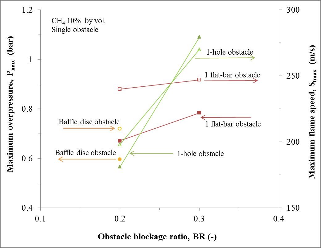
By increasing the obstacle blockage ratio to 0.3 (for 1-hole and 1-flat-bar only), the overpressure in one-hole obstacle was higher (1.1 bar) than the one-flat-bar by an order of 1.4. However, a general trend of increase in overpressure with blockage ratio was discernible in both obstacle shapes. Gardner [9] also noticed an increase in overpressure with blockage ratio up to 0.7 for both hole and flat-bar obstacles with the former higher than the latter from above 0.3 BR.
Also shown in Fig. 6 is the maximum flame speeds from a single obstacle against obstacle blockage ratio for different obstacle shapes. For 0.2 BR obstacles, one-flat-bar obstacle produced the highest maximum flame speeds of about 240 m/s followed by 210 m/s and 198 m/s respectively for baffle disc and one-hole obstacle. This trend was equally witnessed in overpressure records. As the obstacle blockage ratio was increased to 0.3, one-hole obstacle attained a flame speed of nearly 270 m/s which is a factor of 1.12 greater than the one-flat-bar obstacle. It was also seen that the one-hole obstacle was more sensitive to obstacle blockage when compared to the one-flat-bar. The former had an increase in flame speed from 198 m/s to 270 m/s respectively for 0.2 and 0.3 BRs whereas the latter had a nearly constant flame speed that ranged from 240 m/s to 247 m/s for 0.2 and 0.3 blockage ratios in that order.
Flame behaviour during premixed ethylene-air explosions in an enclosed glass cylindrical enclosure of 0.1m diameter and 0.38m length was studied experimentally [8]. Orifice plate, circular plate and wire grids of 0.75, 0.36 and 0.25 blockage ratios respectively were used as obstacles. The fuel-air mixtures had an equivalent ratio of 0.5 and it was ignited via spark plug centrally from one of the end flange using a special ignition system. Orifice plate obstacles were found to provide the maximum combustion overpressures followed by circular plates and wire grid respectively. The comparison is not systematic since each obstacle shape had different obstacle blockage. However, photographic evidence of similar experiments in a glass tube revealed differences in flame propagation and shape downstream of these obstacles. For the orifice plate, the flame passed through the aperture as a jet which led to fast mixture burning downstream. In case of the disc-shaped obstacle, a toroidial flame shape was formed downstream whereas wire-mesh (assumed to be flat-bar type obstacle) split the flame into several flamelets.
Yibin et al. [13] performed an experimental work with methane-air mixtures in a semi-open tube with five different types of obstacle shapes (plates, cuboids, triple prisms, quadruple prism and cylinders) and obstacle blockage ratio of 0.2-0.6. The plates and cylinders could be regarded as flat-bar and baffle disc respectively in the present research. The authors observed that for similar blockage ratios, results showed that plates and triple prisms augmented flame speed and overpressure much larger followed by cuboids while effect of quadruple prisms and cylinders were relatively low. An increase in obstacle blockage also resulted in increase in the explosion severity. High speed photography showed that when the flame approached the obstacles, plates and triple prisms formed a vortex while the flame front of cuboids was also clearly distorted. The flame front of quadruple prism was fairly smooth but the combustion intensity of cylinder was the least in all obstacles.
3. 2. Double obstacles
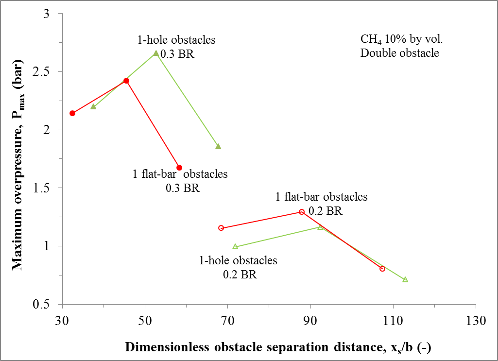
Figure 7 shows the effect of maximum overpressure against dimensionless obstacle spacing with double obstacle of various shapes and blockage ratios. As observed with the single obstacle tests, 1-flat-bar of 0.2 BR produced a greater overpressure of 1.29 bar compared to 0.81 bar for 1-hole obstacles. This is contrary to 0.3 BR where 1-hole obstacles generated about 2.67 bar overpressure whereas 1-flat-bar had 2.42 bar. However for both obstacle blockage and shapes, an influence of obstacle separation was discernible with complete turbulence profiles indicating growth, peak and decay. For a given obstacle blockage, the optimum obstacle spacing for the two obstacle shapes was the same. The 0.3 BR obstacles attained its optimum explosion severity with 1.75 m pitch whereas 0.2 BR was at 2.25 m obstacle spacing. However, due to slightly higher scale effects for the flat-bar obstacles compared to hole-obstacles, the former were noticed to realize their maximum explosion overpressure at a relatively shorter dimensionless distance when related to the 1-hole obstacles. The optimum spacing in the experiments (i.e. 1.75 m and 2.25 m) agreed with the predicted correlation of optimum obstacle spacing from cold flow turbulence given by Na’inna et al. [18].
The relationship between the maximum flame speeds and obstacle spacing with two different obstacle shapes and blockage is given in Fig. 8.
The flame speeds had similar turbulence profile, position to optimum spacing and blockage ratio effect to the maximum overpressure results presented in Fig. 7. For maximum flame speeds with 1-hole obstacles, values of 486 m/s (at 1.75 m obstacle spacing) and 362 m/s (at 2.25 m obstacle spacing) were obtained for 0.3 and 0.2 BRs respectively. However, 463 m/s (at 1.75 m obstacle spacing) and 412 m/s (at 2.25 m obstacle spacing) were accomplished for 0.3 and 0.2 BRs in that order from the 1-flat bar obstacles.
5. Conclusion
The influence of various obstacle shapes (orifice plate, flat-bar and disc baffle) in gas explosions was experimentally studied in a tubular geometry with two obstacles of variable obstacle separation distance using slightly rich methane-air (10% by vol.) as flammable mixtures. Explosions severity in terms of overpressures and flame speeds were measured and systematically analysed.
From single 20% blockage ratio obstacles, maximum explosions overpressures and flame speeds were realized for single-flat bar followed by baffle disc and single-hole obstacles respectively. The duration to peak overpressures and flame exit from the explosion tube was longer for baffle disc obstacle compared to the other obstacles. However, for single obstacles of 30% blockage, the single-hole obstacle produced the highest explosion severity compared to single-flat bar.
For a given obstacle blockage, the optimum obstacle spacing for the two obstacle shapes (1-flat-bar and 1-hole obstacles only) was the same in absolute terms, but due to slightly higher scale effects for the flat-bar obstacles compared to hole-obstacles, the 1-flat-bar obstacles attained their maximum explosion overpressure at a relatively shorter dimensionless distance when related to the 1-hole obstacles.
Single-flat-bar of 0.2 BR produced a greater overpressure and flame speeds compared to 1-hole obstacles, but, the reverse was the case for 0.3 BR. The 0.3 BR obstacles attained its optimum explosion severity with 1.75 m pitch whereas 0.2 BR was at 2.25 m obstacle spacing. Therefore for obstacles of variable blockage ratio and shapes, the influence of obstacle separation was distinct with complete turbulence profiles indicating growth, peak and decay.
Acknowledgements
The authors are thankful to the Nigerian Petroleum Technology Development Fund (PTDF) Overseas Scholarship Scheme, for supporting Abdulmajid Na’inna in his PhD studies on the subject.
References
[1] Phylaktou H.N., Andrews G.E. Prediction of the maximum turbulence intensities generated by grid-plate obstacles in explosion-induced flows// Symp. (Int’l) Combust. – 1994. – V.25, N 1. – P. 103-110.View Article
[2] Bjorkhaug M. Flame acceleration in obstructed radial geometries. PhD Thesis, City University London, London, 1986.
[3] Hjertager B.H. Gas explosions in obstructed vessels [manuscript]. At, Short Course on Explosion Prediction and Mitigation, Deparment of Fuel and Energy, University of Leeds, Leeds, 1993.
[4] Phylaktou H.N. Gas explosions in long closed vessels with obstacles : a turbulent combustion study applicable to industrial explosions. PhD Thesis, University of Leeds, Leeds, 1993.
[5] Van Wingerden C.J.M., Visser J.G., Pasman H.J. Combustion in obstructed diverging and non-diverging flow fields// Combust. React. Kinetics- 22nd Int’l Annual Conf. ICT – 1991.
[6] Lee J.H.S., Knystautas R., Freiman A. High speed turbulent deflagrations and transition to detonation in H2-air mixtures// Combust. Flame. – 1984. V 56, N2. – P. 227-239.View Article
[7] Moen I.O., Bjerketvedt D., Engebretsen T., Jenssen A., Hjertager B.H., Bakke J.R. Transition to detonation in a flame jet// Combust. Flame. – 1989. –V. 75, N 3-4. – P. 297-308.
[8] Starke R., Roth P. An experimental investigation of flame behavior during explosions in cylindrical enclosures with obstacles// Combust Flame. – 1989. – V. 75, N2. – P.111-121.View Article
[9] Gardner C.L. Turbulent combustion in obstacle-accelerated gas explosions - The influence of scale. PhD Thesis, University of Leeds, Leeds, 1998.View Article
[10] Ibrahim S.S., Masri A.R. The effects of obstructions on overpressure resulting from premixed flame deflagration// J. Loss Prevent. Pro. Ind. – 2001. – V. 14, N 3. – P.213-221.View Article
[11] Yu L.X., Sun W.C., Wu C.K. 2002. Flame acceleration and overpressure development in a semiopen tube with repeated obstacles// Proc. Combust. Inst. – 2002. – V.29, N 1. – P. 321-327. View Article
[12] Park D.J., Green A.R., Lee Y.S., Chen Y.C. 2007. Experimental studies on interactions between a freely propagating flame and single obstacles in a rectangular confinement// Combust. Flame. – 2007. – V.150, N 1-2. – P. 27-39.View Article
[13] Yibin D., Fuquan X., Xiaoyan X., Xin C., Hongbin D. 2011. Investigation of solid structure obstacles influence on flame propagation in semi-open tube// Proc. Eng. – 2011. V. 26, - P. 538-544.View Article
[14] Zhou Y.H., Bi M.S., Qi F. 2012. Experimental research into effects of obstacle on methane–coal dust hybrid explosion// J. Loss Prevent. Proc. Ind. – 2012. V.25, N1. – P.127-130.View Article
[15] Xu H., Li Y., Zhu P., Wang X., Zhang H. Experimental study on the mitigation via an ultra-fine water mist of methane/coal dust mixture explosions in the presence of obstacles//J. Loss Prevent. Proc. Ind – 2013. V.26, - P. 815-820.View Article
[16] Yu M., Zheng K., Chu T. Gas explosion flame propagation over various hollow-square obstacles//J. Nat. Gas Sci. Eng. – 2016. V. 30, - P. 221-227.View Article
[17] Na'inna, A.M., Phylaktou H.N., Andrews, G.E. The acceleration of flames in tube explosions with two obstacles as a function of the obstacle separation distance// J. Loss Prevent. Pro. Ind. – 2013. V.26, - P. 1597-1603.View Article
[18] Na'inna, A.M., Phylaktou, H.N., Andrews, G.E.
Effects of obstacle separation distance on gas explosions: the influence of obstacle blockage ratio// Procedia Eng. – 2014. V.84, - P. 306-319.
[19] Na'inna, A.M., Phylaktou, H.N., Andrews, G.E. Explosion flame acceleration over obstacles: Effects of separation distance for a range of scales // Process Saf. Environ. Prot. – 2017. V.107, - P. 309 – 316
[20] Na'inna, A.M., Somuano, G.B., Phylaktou, H.N., Andrews G.E. Flame acceleration in tube explosions with up to three flat-bar obstacles with variable obstacle separation distance// J. Loss Prevent. Process Ind. – 2015. V.38, - P. 119 – 124.
[21] Na’inna, A.M., Phylaktou, H.N., Andrews, G.E. Acceleration of flames in tube explosions with two obstacles as a function of the obstacle separation distance: the influence of mixture reactivity// Proc. 7th Int. Seminar Fire Explosion Hazards. – 2013. – P. 627– 636.
[22] BS5167-2. Measurement of fluid flow by means of pressure differential devices inserted in circular cross-section conduits running full - Part 2: Orifice plates (ISO 5167-2:2003). EU, Brussels, 2003.
[23] Na’inna, A.M., Phylaktou, H.N., Andrews, G.E. Turbulent combustion parameters in gas explosions with two obstacles with variable separation distance. // Proc. 8th Int. Seminar Fire Explosion Hazards. – 2016.