Journal of Fluid Flow, Heat and Mass Transfer (JFFHMT)
ISSN: 2368-6111

Volume 8 - Year 2021 - Pages 33-41
DOI: 10.11159/jffhmt.2021.005
Numerical Simulation of a Radial Free Surface Liquid Jet Impinging on a Heated Surface
Alok Khaware 1, Likitha S. Siddanathi 2, Patrick Sharkey 3, Amine Ben Hadj Ali4, Vinay K. Gupta5
1,5
Ansys Software Pvt Ltd, Research and Development
Plot-34/1 Hinjewadi, Pune, Maharashtra, India, 411057
alok.khaware@ansys.com; vinaykumar.gupta@ansys.com;
2
Luleå University of Technology, Division of Fluid and Experimental Mechanics
Laboratorievägen 14, Luleå, Sweden 97187
likitha.siddanathi@ltu.se
3
Ansys Inc., Research and Development
Milton Park, UK
patrick.sharkey@ansys.com
4
Ansys Germany, GmbH
amine.benhadjali@ansys.com
Abstract - Impinging liquid jets have been demonstrated to be an effective means of providing high heat transfer rates, and widely used in designing cooling systems for electronic modules, plastic manufacturing, and many other applications in the industry. It is very important to study the factors which govern the heat transfer rate in the liquid impingement on a heated surface to ensure cooling efficiency. The paper presents a numerical approach to study the convective heat transfer of circular liquid jet impingement on a heated surface where influencing factors like surface tension, gravity, viscosity, surface temperature etc. are considered. Finite volume method (FVM) with pressure based coupled solver implemented in commercial ANSYS Fluent CFD is used to solve Reynolds Averaged Navier Stokes equations. Free surface flow is modelled using Volume of Fluid (VOF) Method along with the compressive scheme and sharp interface modelling which accurately captures interfaces between immiscible fluids. The liquid film formation and the heat transfer phenomenon are examined in detail. The influence of jet velocity profiles on pressure distribution and heat transfer along the heated surface is presented. The results obtained from numerical solution are validated against experiment and previously published work with a close match.
Keywords: Impinging Liquid Jet, Heat transfer, Volume of Fluid
© Copyright 2021 Authors - This is an Open Access article published under the Creative Commons Attribution License terms Creative Commons Attribution License terms. Unrestricted use, distribution, and reproduction in any medium are permitted, provided the original work is properly cited.
Date Received: 2020-11-13
Date Accepted: 2020-11-14
Date Published: 2021-02-03
Nomenclature
1. Introduction
The investigation of heat transfer during the liquid jet impingement on a heated surface is of interest in the engineering community because an efficient cooling can be achieved by using this technique. When a liquid jet strikes the hot surface, it forms a thin hydrodynamic and thermal boundary layer in the region directly beneath the jet due to the jet deceleration and the resulting increase in pressure. The flow is forced to accelerate in the radial direction parallel to the heated surface which is known as parallel flow zone or wall jet. The zone directly under the jet is called stagnation zone and has a very high heat transfer coefficient. The transport coefficient characteristic of parallel flow persists in the wall jet region. The applications where high heat fluxes are the norm and hot surface temperature is below the boiling temperature of the working liquid, the liquid jet impingement is an attractive cooling option due to its high heat transfer coefficients. The cooling of internal combustion engines, thermal control of high heat dissipating electronic devices, thermal treatment of metals, are few of the applications were liquid jet impingement is well adopted.
In the year 1964, Watson theoretically elucidated the radial spread of
liquid jet over a horizontal plane [
1
]. He divided the complete phenomenon into four regions named as the
stagnation region, the boundary layer region, the fully viscous region, and
the hydraulic jump region. He provided an appropriate detail of boundary
layer formation and described the dominant influence of fluid viscosity
over the complete phenomenon. In 1989, Wang et al. published the
experimental work on conjugate heat transfer between a laminar impinging
jet and a solid disk [
2
]. In the year 1991, Liu and Lienhard proposed a formula capable of
predicting the local Nusselt number
(![]() ) where the variation of the surface heat flux was specified [
3
]. The equations agree well with the experimental data published by Wang.
In the year 1991, Stevens et al. performed an experimental study on a
circular liquid jet impinging onto a perpendicular plate where he
consolidated the effect of velocity on film thickness and heat transfer [
4
]. These theoretical and experimental approaches are very useful to predict
the heat transfer rate, but these cannot be applied easily for the
transient cases or complex systems used in the industry. With the
advancement of computational fluid dynamics in the last two decades, a lot
of researchers had focused on the numerical approach for analysing the flow
and thermal fields in this type of applications. In 2003, Tong et al.
performed the numerical study and showed the influence of jet velocities on
the pressure and heat transfer from the solid surface to the film [
5
]. Fujimoto et al. published their work in 1999 using numerical simulations
[
6
] whereas Edin et al. also predicted pressure distribution and local
Nusselt number variation applying computational modelling in 2015 [
7
].
) where the variation of the surface heat flux was specified [
3
]. The equations agree well with the experimental data published by Wang.
In the year 1991, Stevens et al. performed an experimental study on a
circular liquid jet impinging onto a perpendicular plate where he
consolidated the effect of velocity on film thickness and heat transfer [
4
]. These theoretical and experimental approaches are very useful to predict
the heat transfer rate, but these cannot be applied easily for the
transient cases or complex systems used in the industry. With the
advancement of computational fluid dynamics in the last two decades, a lot
of researchers had focused on the numerical approach for analysing the flow
and thermal fields in this type of applications. In 2003, Tong et al.
performed the numerical study and showed the influence of jet velocities on
the pressure and heat transfer from the solid surface to the film [
5
]. Fujimoto et al. published their work in 1999 using numerical simulations
[
6
] whereas Edin et al. also predicted pressure distribution and local
Nusselt number variation applying computational modelling in 2015 [
7
].
Though the numerical modelling provides an advantage to predict flow field and heat transfer for impinging jets in complicated systems or transient scenarios, it is difficult to model using computational techniques as free surface deforms continuously and does not coincide with the grid. In the present study, the liquid jet impingement on a hot surface is modelled using the Volume of Fluid (VOF) method along with compressive discretization scheme and sharp interface capturing technique. The pressure distribution and Nu variation are validated against experiment and previously published numerical results.
2. Overview of Numerical Methods
2.1 Governing Equations
The governing equations for CFD are based on conservation of mass, momentum, and energy which are solved using the Finite Volume Method (FVM). The volume fraction equation is solved to identify the interfaces between immiscible fluids by an indicator function. Consider the instance of two co-flowing fluids (a primary and secondary fluid) - there are three possibilities as to how the fluids can fill a given computational cell, if the volume fraction of the primary fluid in the cell is denoted by α, then α = 1 means that the cell is completely filled with the primary fluid whereas α = 0 means the cell is completely filled with the secondary fluid and 0 < α < 1 means that the cell is partially filled and contains the interface.
Summation of volume fraction for all the fluids should be equal to one.

The volume fraction equation in the absence of mass sources is given as
For VOF model, a single momentum equation is solved throughout the domain and the resulting velocity field is shared among the phases.
Where ![]() are represented as density, pressure, velocity vector, stress tensor, body force and time respectively. The properties used in the momentum equation are volume-weighted averaged properties.
are represented as density, pressure, velocity vector, stress tensor, body force and time respectively. The properties used in the momentum equation are volume-weighted averaged properties.
The continuity equations for steady state incompressible flow can be formulated as,

The energy equation which is also shared among the phases is as follows

Where, E is the total energy, Keff is the effective conductivity, Sh represents the volumetric heat sources.
2. 2. Pressure Velocity Coupling
The pressure-based solver allows the solution of the flow problem either in segregated or coupled manner. There are multiple algorithms such as SIMPLE, SIMPLEC and PISO that follow the segregated approach for solving momentum and continuity equations. The Coupled approach solves the momentum and pressure-based continuity equations together and thus provides a robust and superior performance compared to the segregated approach. The full implicit coupling is achieved through an implicit discretization of pressure gradient terms in the momentum equations, and an implicit discretization of the face mass flux, including the Rhie-Chow pressure dissipation terms [ 8 ].
In the coupled approach, the momentum and continuity equations in the delta form could be represented as follows
Where,![]() is the coefficient matrix,
is the coefficient matrix, ![]() is the pressure coefficient;
is the pressure coefficient; ![]() ,
, ![]() ,
, ![]() and
and ![]() , are the coefficients velocity
coupled with pressure;
, are the coefficients velocity
coupled with pressure; ![]() ,
,![]() ,
,![]() and
and ![]() are the velocity coefficients coupled
with each other,
are the velocity coefficients coupled
with each other, ![]() is the solution vector containing
is the solution vector containing ![]() for pressure correction and
for pressure correction and ![]() ,
, ![]() for velocity corrections and
for velocity corrections and ![]() is the residual vector.
is the residual vector.
2.3. Coupling Volume Fraction Discretization using Compressive Scheme
In volume fraction equation, face values of volume fraction used in the convection term are discretized using a modified compressive scheme available in ANSYS Fluent which is a second-order reconstruction scheme based on slope limiters limiters [ 8 ].
Where,
![]() is face volume fraction,
is face volume fraction, ![]() is donor cell volume fraction,
is donor cell volume fraction, ![]() is the slope limiter with the maximum
value of 2,
is the slope limiter with the maximum
value of 2, ![]() is interface normal for donor cell
and
is interface normal for donor cell
and ![]() is the position vector between donor
cell centroid and face centroid.
is the position vector between donor
cell centroid and face centroid.
2.4. Coupling Surface Tension Modelling at the Interface
The Continuum Surface Force (CSF) model of Brackbill [ 9 ] is the widely used model for surface tension force calculation at the interface. To model the pressure-jump across the interface, a surface force after being converted to volumetric form is added in the momentum equation.
The curvature, K, is defined in terms of the divergence of the unit normal to the interface, ![]() .
.

Where, ![]()
3. Validation Studies
3.1. Problem Description
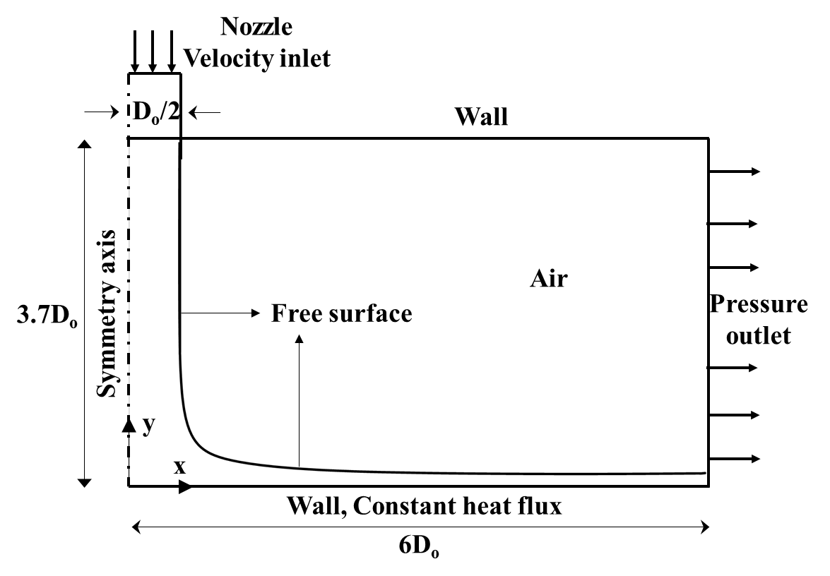
The objective of this study is to investigate the impact of velocity profile and grid resolution on the liquid film thickness and heat transfer for the impinging liquid jet on a heated surface and validate numerical results against experimental. The analysis is carried out on a 2D axis-symmetric rectangular section as shown in Figure 1. The water jet is injected through the nozzle with a diameter (D0) of 4.06 mm. The water jet strikes the heated surface which has a constant heat flux of 149000 W/m², and spreads across surface forming a film as shown in the Figure 1. The rest of the domain is filled with air. The top surface is considered as an adiabatic wall whereas the right-side surface is defined as the pressure outlet with the atmospheric pressure. The flow is considered as laminar and turbulence effects are neglected in the current study as the film formed is very thin. The occurrence of hydraulic jump across the domain is also neglected. The temperature dependence is included for the properties such as viscosity, surface tension, and thermal conductivity along with the influence of gravity.
A uniform quadrilateral mesh is created for the analysis. The maximum orthogonal quality of the mesh is close to 1, whereas the aspect ratio is about 13.11. The mesh is resolved sufficiently near the heated wall.
3.2. Solution Methodology
The case study is performed using implicit volume fraction formulation. Compressive and Second Order Upwind schemes are used for volume fraction and momentum discretization, respectively to achieve better accuracy and convergence. Sharp interface capturing scheme is applied to maintain the crisp free surface. Pressure is discretized using PRESTO! (PREssure STaggering Option). Pressure and velocities are solved in a coupled manner, whereas volume fraction is solved in a segregated manner. Water is considered as the primary phase at inlet temperature of 298 K whereas air as an incompressible fluid is considered for the secondary phase at the same temperature. The thermophysical properties such as kinematic viscosity, thermal conductivity, and surface tension are defined using the following piecewise polynomial functions.

3.3. Results and Discussion
A grid independence study is first conducted for the case. The study continued with the detail investigation of the influence of jet velocity profile where the development of free surface, variations in pressure, and the Nusselt number (Nu) across the heated surface are validated against the experiment and already published computational works ([ 4 ], [ 5 ] and [ 7 ]). The Nusselt number ( Nu) is the characterization of the distribution of temperature and heat flux. The pressure is normalized by dividing with stagnation pressure. The pressure at the wall in the first boundary cell near the axis of symmetry is considered as the stagnation pressure. Once the solution reaches a steady state, the Nu number is calculated based on the temperature variations across the heated surface where nozzle diameter is considered as the characteristic length. Nu across the heated surface can be expressed as,
Where, qw is the constant heat flux on the wall, kw is the thermal conductivity, Tw is the wall temperature and Tref (300 K) is the reference temperature.
3.3.1. Grid Independence Study
The grid independence study is conducted on four different meshes as shown in Table 1. The mesh is resolved near the boundary. The analysis is carried out using a uniform velocity at inlet and results are compared against the published paper by Edin et al. 7 . The numerically obtained results are also validated against experiment.
Table 1. Mesh information for grid independent study.
| Mesh | Cell Count | First layer height at heated surface (m) |
| Mesh1 | 3464 | 5e-6 |
| Mesh2 | 56800 | 2e-6 |
| Mesh3 | 229000 | 1e-6 |
| Mesh4 | 908800 | 5e-7 |
The Figure 2 shows the pressure variations for different meshes and the results are almost identical to the result obtained by Edin et al. The Figure 3 shows the Nu variations for different meshes along with Steven’s experimental result and Edin’s published data.
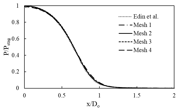
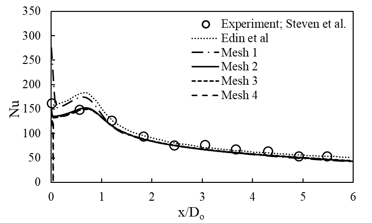
It can be observed that Mesh 1 result deviates from the experiment whereas all other mesh results are almost identical and close to the experiment. Therefore, Mesh 2 is considered for further simulations for computational efficiency.
3.3.2. Influence of Jet Velocity Profiles
The inlet velocity of the jet is the most critical factor that influences the convective heat transfer and stagnation region. In this case study, the influence of uniform velocity and one-seventh power law which corresponds to the case of fully developed turbulent flow are investigated. In the case where a turbulent issuing from the jet is assumed, the flow is relaminarized as it impinges onto the surface and stays laminar until the laminar-to-turbulent transition occurs. The laminar region upstream of the transition point is the focus area in the current work. The Reynolds number (Re) is considered as 10600 for both the variants based on nozzle diameter. The uniform velocity normal to the boundary and in the direction of axis can be expressed as,
The profile velocity normal to the boundary can be expressed as
Where,
![]() and
and ![]()
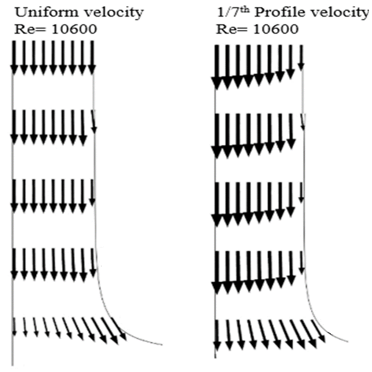
The axial velocity profile is shown in the Figure 4 for both the variants. In the uniform velocity case, the velocity profiles are flat at the beginning and a local velocity peak is developed which moves slightly outward as the jet approaches the wall. On the other hand, the one-seventh power law case shows that the velocity profile gets flattened as the flow approaches towards wall. The vertical velocity profile has significant effects on the convective heat transfer, particularly in the stagnation region. The local peak in vertical velocity for the uniform velocity case leads to a local maximum in heat transfer. A monotonically decreasing vertical velocity profile prevail the one-seventh power case and local maximum in heat transfer does not appear.
3.3.3. Free Surface Formation for Different Velocity Profiles
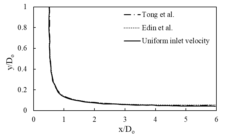
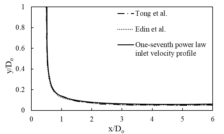
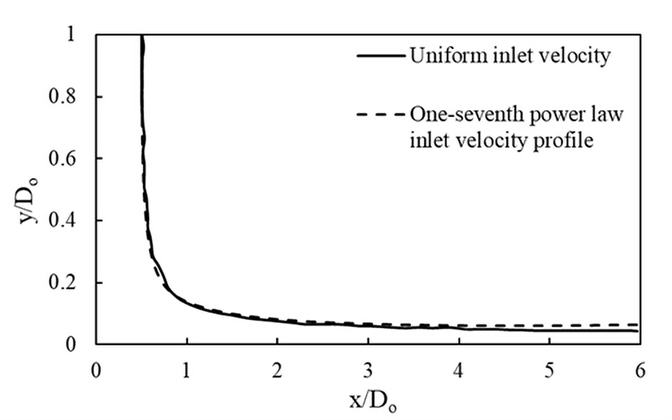
The free surface is the interface region between the water jet and air. Figure 5 shows the free surface formed for uniform velocity case whereas the Figure 6 shows the free surface formed for one-seventh power law velocity profile case. Figure 7 shows the comparison of free surface from both the variants. In both cases, a stagnation zone is formed around the impact point, followed by the formation of the velocity boundary layer. Further, the velocity boundary layer thickens and absorbs the entire flow after a certain distance from the impact point. The results obtained are validated with the previous computational works of Tong et al. and Edin et al. with a close agreement [5], [7].
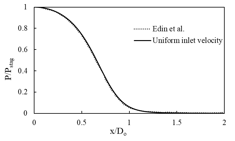
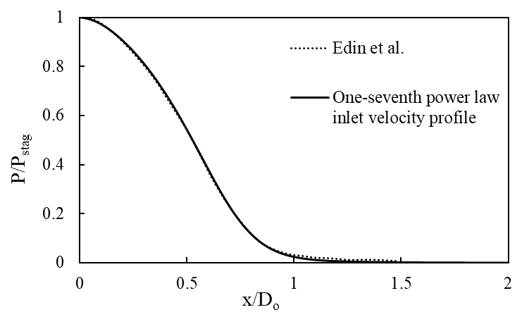
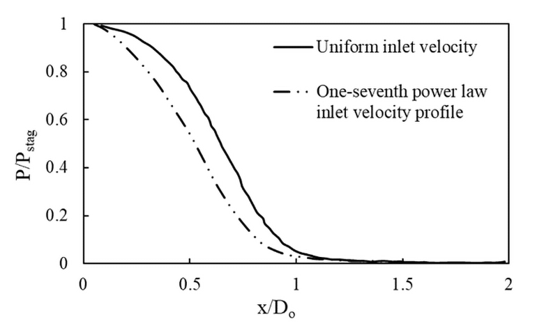
3.3.4. Pressure Variations for Different Velocity Profiles
Figure 8 and Figure 9 show the pressure variations across the heated surface for uniform velocity case and one-seventh power law velocity profile case, respectively. In both cases, the maximum pressure is observed at the stagnation region and further decreases monotonically to zero as the jet moves across the plate. The results obtained are verified with the Edin et al. results with a close agreement. Figure 10 shows that the stagnation region for the one-seventh power law velocity profile case is slightly narrow than the uniform velocity case. The large variation in the jet velocity results a rapid change in pressure and subsequently narrows the stagnation region.
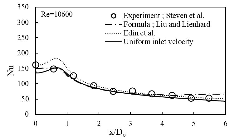
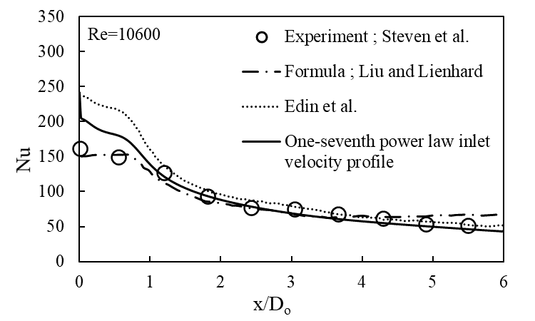
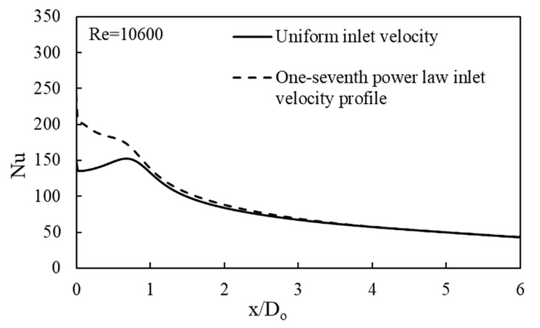
3.3.5. Nusselt number (Nu) Variations for Different Velocity Profiles
Figure 11 and Figure 12 show the Nusselt number variations across the heated surface for uniform velocity case and one-seventh power law velocity profile case, respectively. The comparison of Nu variation from both the variants are plotted in the Figure 13. In the uniform velocity case, a local peak in the Nu at the stagnation region is observed due to local maximum heat transfer. Whereas the peak is not observed in the profile case as the velocity profile decreases monotonically and prevents the formation of local maximum heat transfer. Further, as the flow reaches away from the stagnation zone, a decrement in Nu across the surface is observed in both the cases. The results obtained are validated against the experiment done by Steven et al. [4]. The results are also compared with the formula proposed by Liu [3] and the numerical work done by Edin et al. [7]. The present results for Nu distribution are in a good agreement with all of the previous referenced results.
4. Conclusion
In the present study, the heat transfer efficiency of a radial free surface liquid impingement on a heated surface is studied numerically using VOF method implemented in ANSYS Fluent CFD solver. The steady-state analysis is carried out on a 2D axi-symmetric geometry by considering the flow as laminar. The dependency of thermophysical properties on temperature is included along with gravity, whereas the effects of turbulence are neglected. A grid independence study is conducted on four different meshes and it is observed that the mesh needs to resolve sufficiently on the heated surface boundary to predict the heat transfer accurately. The impact of inlet jet velocity profile is studied in detail by using a uniform jet velocity and one-seventh power law of velocity profile. The free surface formation, pressure and Nusselt number variation across the heated surface is validated against experiment. The results are also verified with the proposed formula and previously published computational works. All the results obtained from the current work are in a good agreement with the experiment and reference data.
References
[1] E. J. Watson, "The radial spread of a liquid jet over a horizontal plane," Journal of Fluid Mechanics, pp. 481-499, 1964. View Article
[2] X. Wang, Z. Dagan and L. Jiji, "Conjugate heat transfer between a laminar impinging liquid jet and a solid disk," International Journal of Heat and Mass Transfer, pp. 2189-2197, 1989. View Article
[3] X. Liu, J. H. Lienhard and J. S. Lombara, "Convective heat transfer by impingement of circular liquid jets," Journal of Heat Transfer, pp. 571-582, 1991. View Article
[4] J. Stevens and B. W. Webb, "Local heat transfer coefficients under an axisymmetric, single-phase liquid jet," Journal of Heat Transfer, pp. 71-78, 1991. View Article
[5] A. Y. Tong, "A numerical study on the hydrodynamics and heat transfer of a circular liquid jet impinging onto a substrate," Numerical Heat Transfer: Part A: Applications, vol. 44, no. 1, pp. 1-19, 2003. View Article
[6] H. Fujimoto, N. Hatta and R. Viskanta, "Numerical simulation of convective heat transfer to a radial free surface jet impinging on a hot solid," Heat and Mass Transfer, vol. 35, no. 4, pp. 266-272, 1999. View Article
[7] B. Edin and Š. Šefko, "Computational modeling and simulation of nonisothermal free-surface flow of a liquid jet impinging on a heated surface," Procedia Engineering 100, pp. 115-124, 2015. View Article
[8] Ansys Inc., "ANSYS Fluent Theory Guide, Release 19.3," 2019.
[9] J. U. Brackbill, D. B. Kothe and C. Zemach, "A Continuum Method for Modeling Surface Tension," Journal of Computational Physics, pp. 335-354, 1992. View Article