Journal of Fluid Flow, Heat and Mass Transfer (JFFHMT)
ISSN: 2368-6111

Volume 7 - Year 2020 - Pages 37-45
DOI: 10.11159/jffhmt.2020.004
Numerical Simulation of Laminar Vortex-Shedding Flow around a very Slender and Rectangular Bluff Body
Amin Etminan1, Armin Bodaghkhani2, Yuri S. Muzychka1
1Department of Mechanical Engineering, Memorial University of Newfoundland (MUN)
St. John’s, NL, Canada A1A 3X5
aetminan@mun.ca; yurim@mun.ca
2Faculty of Sustainable Design Engineering, University of Prince Edward Island (UPEI)
Charlottetown, PEI, Canada C1A 4P3
abodaghkhani@upei.ca
Abstract - In the present study, the numerical results of flow and heat transfer structure around a very slender bluff body with a rectangular cross-sectional area are investigated in detail. The Reynolds number is considered so low that the flow presumably is laminar. Reynolds number, Prandtl number, aspect ratio and the angle of incidence are assumed to be 100, 0.71, 0.1 and 45 degrees respectively. An in-house finite volume computer code using the SIMPLEC algorithm and non-staggered grid is employed for the simulations in the two-dimensional and incompressible flow regime. The study of spatial resolution and grid independency is carried out as well. Furthermore, the instantaneous variations of flow parameters are provided and discussed thoroughly. The global quantities including pressure and viscous drag and lift coefficients, the Root Mean Square (RMS) of drag and lift, and Strouhal number are also computed. The simulations reveal that the angle of incidence of the bluff body relocates the stagnation point from the centre to a point at the one-sixteenth of frontal side. An acceptable verification has been observed by making a comparison between the provided results and available data in the literature.
Keywords: Slender bluff body, SIMPLEC algorithm, Unsteady flow, Vortex shedding, Heat transfer.
© Copyright 2020 Authors - This is an Open Access article published under the Creative Commons Attribution License terms Creative Commons Attribution License terms. Unrestricted use, distribution, and reproduction in any medium are permitted, provided the original work is properly cited.
Date Received: 2020-08-26
Date Accepted: 2020-10-16
Date Published: 2020-11-16
1. Introduction
The prediction and analysis of flow characteristics over slender bluff bodies have recently attracted significant attention in the field of aerodynamics and wind engineering. The essential and practical importance of an understanding of flow behavior around bluff bodies is still demanded by mechanical and aeronautical engineers. Despite the simple geometry of common bluff body objects such as square, circular, and rectangular, the flow analysis around them is very complicated. However, due to the complexity of the flow that usually come across bluff bodies, the prediction of lift and drag forces, frequency of eddy shedding, and pressure distribution still disclose many curious facts for investigators. In recent decades, Computational Fluid Dynamics (CFD) has become one of the most popular and efficient method for the analysis of the flow structure in the early stage of each real construction and manufacturing process. Flow separation, vortex shedding, fluctuating lift and drag forces, vibration, noise, and heat transfer patterns around bluff bodies were extensively investigated by researchers, i.e., [1]-[10].
The effect of the orientation of a square cylinder on flow characteristics has been experimentally studied by [11]. The angle of incidence was ranged from 0 to 60 degrees, and the Reynolds number was changed from 1340 to 9980. Their results disclosed that flow separation points were located at the leading edge of the cylinder with zero inclination. When the angle of orientation was greater than zero, the location of separation points was moved downstream, and the size of the wake region was increased. They also found that an increase in the angle of incidence caused a smaller drag coefficient and a higher Strouhal number. Particle Image Velocimetry (PIV) was used by [12] to capture the vortex shedding phenomenon caused by flow passing a two-dimensional square cylinder at incidence for Reynolds numbers of 4000, 10000, and 20000. A comprehensive study on the vortex shedding process and the coherent large-scale flow unsteadiness were done by them.
The flow pattern around a square cylinder with two aspect ratios of 16 and 28, an angle of incidence between 0 and 45 degrees and a Reynolds number of 410 was investigated by [13]. PIV along with hot wire anemometry, was utilized to find flow parameters such as velocity, pressure, and fluctuations. The lowest drag coefficient and highest Strouhal number was found at 22.5° of incidence. The flow visualization images revealed that the streamwise space between the alternating vortices in the downstream was depended on the angle of incidence. They also observed that the drag coefficient was decreased and the Strouhal number was increased as the aspect ratio was enhanced.
Flow around a rectangular bluff body with an aspect ratio of 1:5 was studied by [14] using a high-pressure wind tunnel. By making a comparison between two angles of incidence; α=0 and 45 degrees, it was found that the distribution of the lift coefficient caused a reattachment for α=0° and consequently empowered the vortex shedding phenomenon.
The aerodynamic behavior of rectangular bluff body with an aspect ratio of 1:5 was investigated by [15], [16] numerically and experimentally. In their comprehensive studies, all details of flow involving pressure distribution on the cylinder, drag and lift forces, as well as the vortex shedding phenomenon were investigated using a wind tunnel for unsteady high Reynolds number flow regime. They found that the size of the recirculation region near the lateral walls of the cylinder was decreased versus free-stream turbulence. They also showed that turbulence level affected the vortex shedding mechanism significantly and made the vibration of the flexible cylinder consequently. Wake measurement was done by a slight Reynolds number dependence of the Strouhal number frequency. Both numerical and experimental studies of flow structure around a rectangular bluff body with an aspect ratio of 5:1 was carried out by [17] using Large Eddy Simulation (LES). Two moderate and high turbulence inlets were considered as inlet boundary conditions. They found that shear layer instabilities appeared adjacent to the leading edge of the bluff body when the strong level of inlet turbulence flow was considered. Therefore, this instability made a higher shear layer curvature and a shorter reattachment length as well.
The main purpose of this numerical study is to investigate the incoming free-stream flow influence on aerodynamic forces applied on and heat transfer characteristics from a very slender bluff body with rectangular cross section area and sharp corners. Regarding the assumed Reynolds number, the flow regime is remained laminar. A comprehensive grid study is carried out to reveal optimal mesh size.
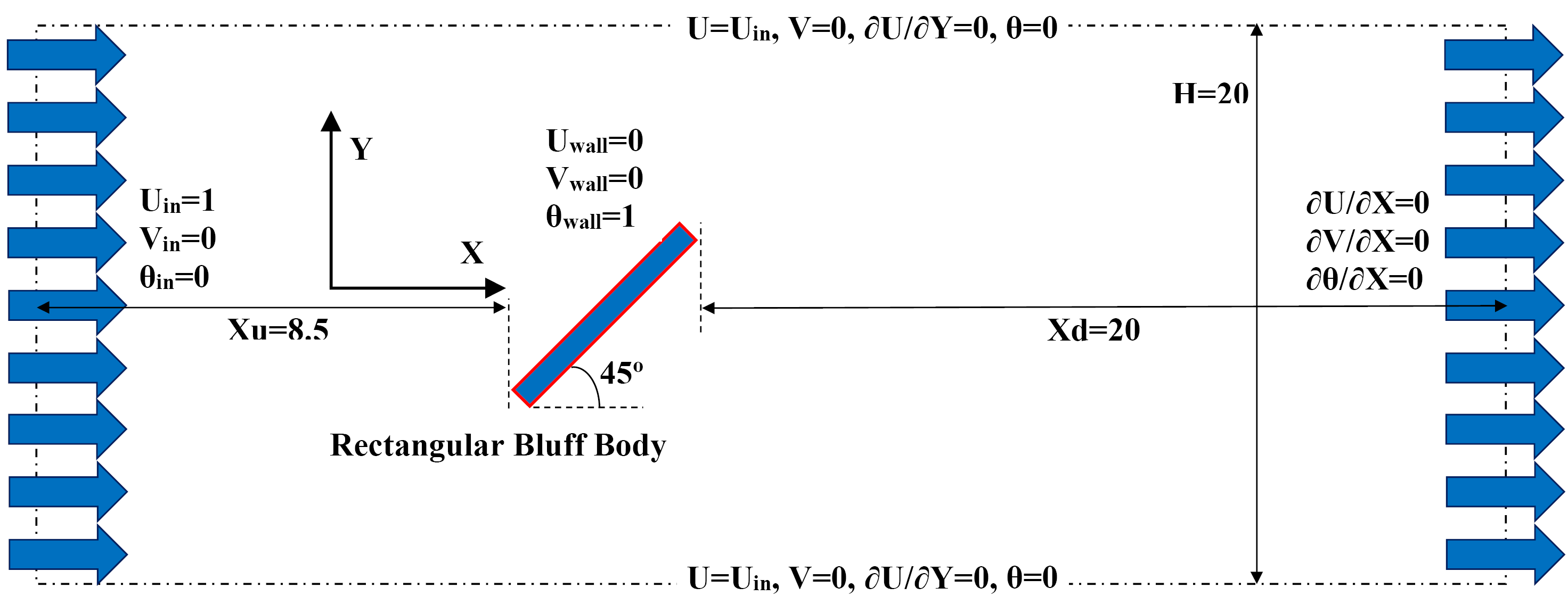
It is found that the vortex shedding phenomenon made by rectangular vortex generator can affect all fluid and thermal parameters throughout computational domains particularly downstream flow. The assumed boundary conditions and geometrical constants are presented in Figure 1. Based on this figure, the dimensionless height of the domain is 20; upstream distance is 8.5 and downstream distance is 20. These constant values are suggested by several comprehensive studies such as [18]-[21]. The inlet X-velocity component of 1.0 is applied to the entrance while the fully developed boundary condition is employed at flow output as well. It means that downstream distance is long enough that all flow parameters have no variation in X-direction. Moreover, two other sides of the domain are presumed far-field. It also indicates that these boundaries are not affected by the boundary layer created by the solid walls of the vortex generator. Eventually, no-slip boundary condition and constant wall temperature are considered on the heated bluff body where placed at 45° of incidence (see Figure 1).
2. Computational Method
The numerical analysis includes continuity, Navier-Stokes, energy and other related equations for simulation of flow and heat transfer characteristics around the described bluff body. All simulations are done for two-dimensional, incompressible, Newtonian and unsteady-periodic flow. The governing equations in dimensionless form are as follows:

where
The Reynolds, Strouhal and Prandtl numbers are defined as follows:


where d, f, t, T, ρ, υ, and α correspond to the projection of vortex generator height/width, the frequency of eddy shedding, time, temperature, density, kinematic viscosity and thermal diffusion of fluid respectively. The capitalized X and Y are dimensionless coordinate axes which are defined as x/d and y/d, respectively. Furthermore, constant density, viscosity and dimensionless time-step of Δτ=0.025 are considered to all simulations. An in-house computer code employing collocated variables has been utilized to transform the partial differential equations to algebraic equations by finite volume method. The velocity-pressure coupling in the governing equations is based on the algorithm of the semi-implicit method for pressure linked equations-consistent (SIMPLEC), and a second-order Crank–Nicolson scheme is utilized. The second-order upwind differencing scheme is applied for the spatial discretization of the pressure and momentum terms. To compute the global parameters such as aerodynamic forces, Strouhal number, drag and lift coefficients, and the RMS of these forces, a sampling time of 10 predominant vortex shedding cycles are considered.
3. Grid Generation
According to Figure 1, the computational domain is a rectangle with a dimensionless size of 20⨯29.5. This area must be discretized to very small finite volumes to capture all flow phenomena, particularly near the bluff body where flow separation, reverse flow, pressure gradient and shear flow are dominant matter.
Figure 2. The schematic of grid generation (a) whole domain, (b) zoomed-in view of the area around the vortex generator.
As illustrated in Figure 2(a), quadrilateral meshes are generated entire the computational domain. With the first grid minimal setting 0.0005 away from the bluff body walls, the grids are stretched gradually with an expansion rate of 1.02 for 1×d dimension in both X- and Y-directions from the solid walls of the bluff body (see the enlarged view in Figure 2(b) for more details).
4. Numerical Approach Validation
In all numerical simulation data validation is intended to make certain, well-defined, accurate, and precise numerical procedure as well as results. Table 1 shows some of the both numerical and experimental results in the literature for a single square bluff body at angle of attack zero. According to the data in Table 1, an acceptable agreement is observed between present study and others’ results. Some differences between results are rooted in solution methods, different Reynolds number and geometrical details.
Table 1. validation of the numerical procedure by experimental and numerical data in the literature.
| Ref. | Method | Cd | Cdp | St |
|---|---|---|---|---|
| Present Study | Num. | 1.49 | 1.44 | 0.147 |
| Sohankar and Etminan [6] | Num. | 1.48 | 1.44 | 0.146 |
| Sharma and Eswaran [22] | Num. | 1.50 | 1.44 | 0.149 |
| Gera et al. [23] | Num. | 1.46 | 1.44 | 0.129 |
| Sohankar et al. [24] | Num. | 1.44 | 1.4 | 0.143 |
| Shimizu and Tanida [25] | Exp. | 1.58 | N/A | 0.133 |
5. Mesh Independency Study
A mesh independency study is carried out to find an optimal number of cells and the impact of the number of cells on the flow parameters, i.e. mean drag coefficient and Strouhal number. Five non-uniform and structured cases of generated mesh including 24140, 32144, 38700, 46295 and 56680 volumes are provided to distinguish an independent grid number. Therefore, the variations of the drag coefficient and Strouhal number versus five mentioned grid cases are presented in Figure 3. This figure clearly demonstrates a negligible deviation between the mentioned flow parameters for the grid number of 46295 and 56680. Consequently, grid number of 46295 should be selected to minimize the computational time for all following simulations.
6. Numerical Results and Discussion
Figure 4 illustrates, where the time-histories of the lift and drag coefficients are drawn, the steady flow changes into an unsteady-periodic regime after a specific
time, and these forces apply to the bluff body periodically with a constant frequency. It means that as the time-marching process is commenced, the time-histories experienced a transient start-up process reaching a fully saturated periodic flow. The period of the transient time depends on initial conditions, the Reynolds number, the aspect ratio and the angle of incidence of the bluff body (as it mentioned by [18]), which is about τ=25 as it recognizable from Figure 4. In this case the amplitude of drag force is 0.51 and 46% greater than the lift. Meanwhile, the time-mean of total drag and lift forces are 1.63 and 0.18 respectively (see Table 1 for further details.). Interestingly, it is also recognized that more than 95% of the drag force is belonged to the pressure component, but just one-third of the lift force is rooted in the pressure component.
One complete cycle of the lift coefficient in a fully periodic flow regime is illustrated in Figure 5 simultaneous with one cycle of drag coefficient. As it clearly seen, these forces are antiphase, with a phase lag of π (180 degrees). It means that the maximum value of the lift coefficient (the point labelled with b) happens when the drag coefficient is at the lowest value (the point labelled with b') and vice versa. On the other hand, the mean values of both coefficients (the points labelled with c and c') do not be happened at the same time. This time lag is caused by a dominant component of drag force which is produced by the considerable streamwise pressure gradient between frontal and rear sides of the bluff body.
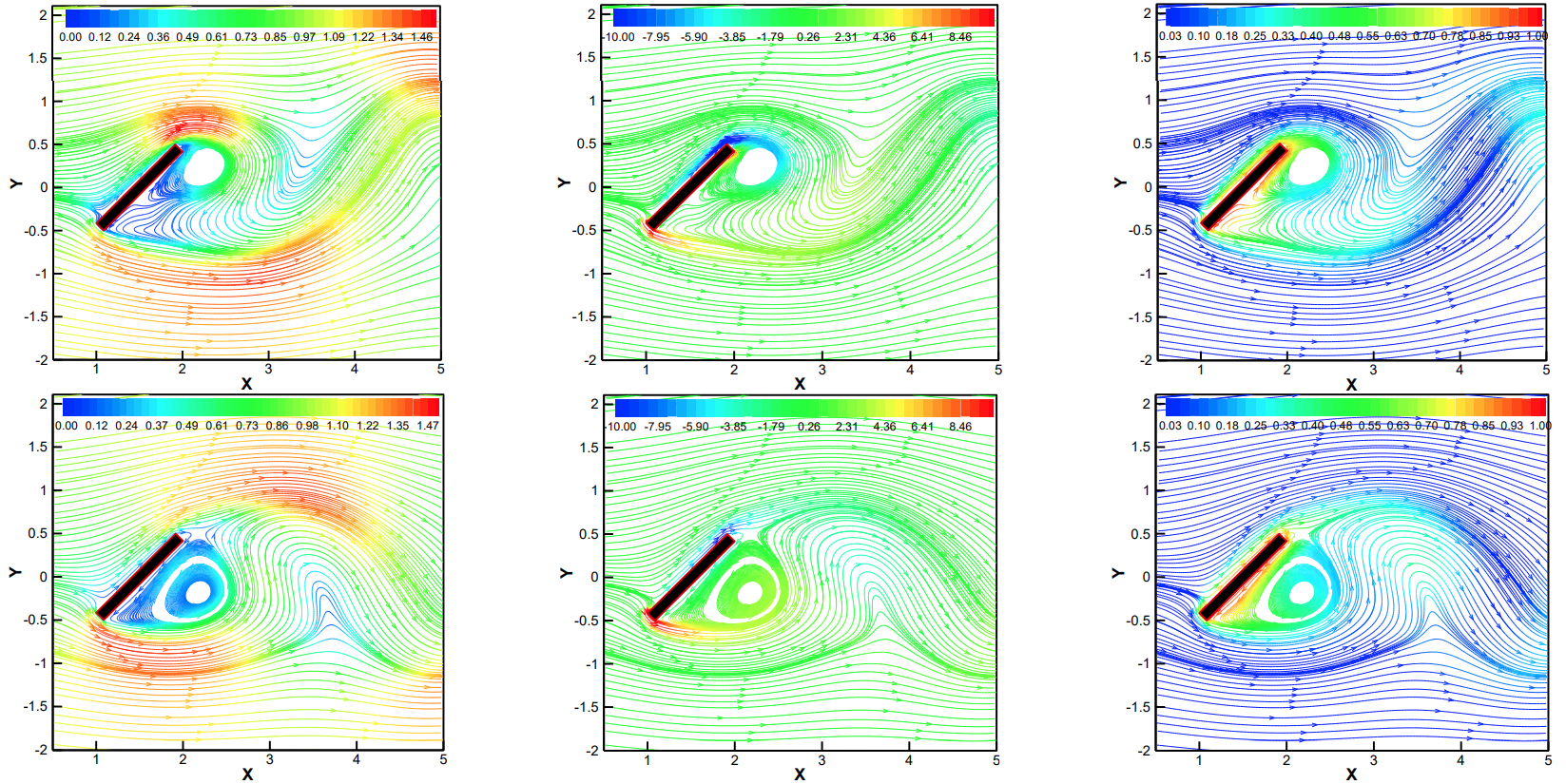
To have a clear and deep understanding of the physics of the flow, instantaneous streamlines are colored by velocity, vorticity and temperature at two important moments; the maximum values of lift and drag coefficients, in which are shown in Figure 6. According to the results, the Y-velocity difference between frontal and rear regions of the bluff body is remarkable and causes maximum lift force as well. Meanwhile, the X-velocity component is experienced the highest difference between the frontal and rear sides and makes the maxi-
Figure 4. Time-histories of (a) lift and (b) drag coefficients (two zoomed-in views are also illustrated for more details)
-mum drag coefficient accordingly. Besides, the position of the low-pressure vortex region behind the bluff body is located at the top-rear corner of the bluff body, providing the possibility of maximum lift force (centre column in Figure 6) while the centre of wake region is located in the horizontal direction of the bluff body, in which creates the maximum drag force as well.
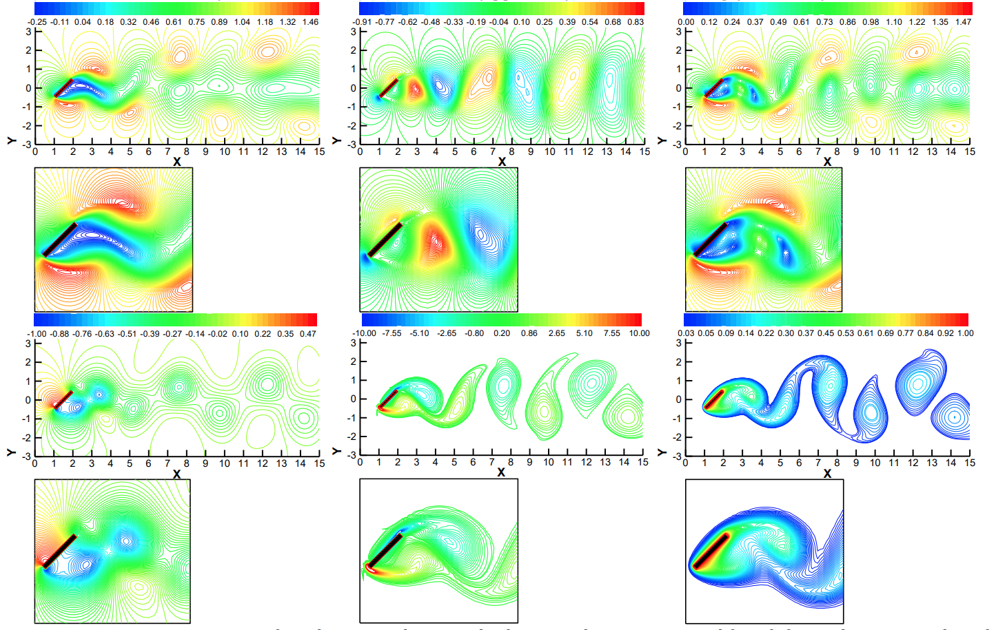
The instantaneous patterns of some of the flow parameters are shown in Figure 7. The negative X- velocity component behind the bluff body means the movement of the wake region of the flow to the upstream
, which is clearly depicted in Figure 7. By moving away from the solid walls, flow velocity is recovered as the inlet flow. By having a look at the velocity components and vorticity contours simultaneously, it is found that the upward and downward Y-velocity in combination with the X-component push the vorticity regions towards the downstream frequently. Thus, the stagnation point of flow on the frontal side of the bluff body is located at the bottom one-fifth. The exact position of this point depends on the angle of incidence and inlet flow direction as well.
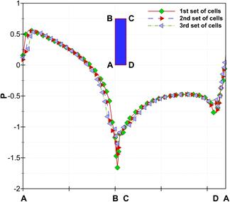
Figure 8 shows the instantaneous non-dimensional pressure distribution on the walls (labeled by the 1st set of cells), and so close to the walls (labeled by the 2nd and 3rd sets of cells) at the moment of maximum lift force. As expected, the highest pressure occurs on the side AB where the incoming flow hits that at first. Hence, a stagnation point is located at a short distance of 0.0625 from point A toward point B where the stagnation pressure is 0.5625. At the moment of maximum lift, the high-velocity region is located near the side BC where the lowest pressure is there. A low-pressure distribution is on the side CD where a big wake region is presented. Regarding Figure 7, the centre of the wake region is closer to the top-rear corner of the bluff body indicating the lowest value of pressure over that zone which can be realized in Figure 8 as well. Figure 8 also displays pressure distribution around the bluff body in the 2nd and 3rd sets of cells where the largest deviation happened near the stagnation point and the top-front corner
indicating the lowest pressure region.
The distributions of horizontal and vertical components of velocity on the axis of the computational domain have been illustrated in Figure 9(a) at the moment of maximum lift force. Based on Figure 9(a), the kinetic energy of the uniform velocity inlet flow is changing to the pressure head as the flow goes closer to the bluff body to set to the amount of zero on the wall satisfying no-slip boundary condition on the walls. It can be seen in Figure 9(a), the X-velocity is negative in the wake region over a distance of 3d. Then, X-velocity shows fluctuating behavior due to the vortex shedding which is damped in the downstream to reach a value of 0.5 before leaving the domain. While the presence of the bluff body and the stagnation condition force the incoming flow redirects toward the front top and bottom corners displayed by V in Figure 9(a).
The rotational effects of the vortex regions in the downstream also cause a greater fluctuation in Y-velocity compared to X-velocity. According to Figure 9(b), the lowest pressure happens at the centre of the wake region behind the bluff body (X⁓2). Afterwards, the pressure would be recovered as the inertia of the far-field flow and momentum transport affect the downstream flow pattern significantly. Eventually, the temperature distribution follows a fluctuating trend coincident with the vortex shedding in the downstream where the thermal energy transport phenomenon occurs.
the schematic of the bluff body in this figure is at 45°)
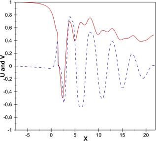
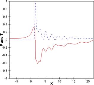
Figure 9. Distributions of (a) velocity components, (b) pressure and temperature on the axis.
(solid line is for U and P, and dashed line is for V and T)
7. Conclusions
Numerical computation of laminar vortex shedding around a very slender vortex generator with a rectangular cross-section area is carried out for Reynolds number of 100, Prandtl number of 0.71, the aspect ratio of 0.1 and the angle of incidence of 45 degrees. It is found that after a specific time the eddy will shed in downstream with a constant frequency. Due to the 45 degrees angle of incidence of the bluff body, more than 95% of net drag and one-third of lift forces are related to the pressure component. It is also observed that the sinusoidal drag and lift forces have a 180-degree phase lag. This means that maximum drag force occurs simultaneously with minimum lift force and vice versa. In addition, the flow separation points are located at the leading and trailing edges of top and bottom sides respectively where the maximum value of vorticity is created. Eventually, the stagnation point of flow occurs at the bottom one-sixteenth of the frontal side of the bluff body. The value of the angle of incidence causes this movement from the centre of the frontal side to an end.
Acknowledgment
The research was supported by NSERC through the Discovery Grants program.
References
[1] R. King and D.J. Johns, “Wake interaction experiments with two flexible circular cylinders in flowing water,” Journal of Sound and Vibration, vol. 45(2), pp. 259–283, 1976.View Article
[2] M.M. Zdravkovich and D.L. Pridden, “Interference between two circular cylinders; series of unexpected discontinuities,” Journal of Wind Engineering and Industrial Aerodynamics, vol. 2(3), pp. 255–270, 1977.View Article
[3] M.M. Alam, M. Moriya, K. Takai and H. Sakamoto, “Fluctuating fluid forces acting on two circular cylinders in a tandem arrangement at a subcritical Reynolds number,” Journal of Wind Engineering and Industrial Aerodynamics, vol. 91(1–2), pp. 139–154, 2003.View Article
[4] M.M. Alam and Y. Zhou, “Phase lag between vortex shedding from two tandem bluff bodies,” Journal of Fluids and Structures, vol. 23(2), pp. 339–347, 2007.View Article
[5] T. Kitagawa and H. Ohta, “Numerical investigation on flow around circular cylinders in the tandem arrangement at a subcritical Reynolds number,” Journal of Fluids and Structures, vol. 24(5), pp. 680–699, 2008.View Article
[6] A. Sohankar and A. Etminan, “Forced-convection heat transfer from tandem square cylinders in cross flow at low Reynolds numbers,” International Journal for Numerical Methods in Fluids, vol. 60, pp. 733–751, 2009.View Article
[7] S. Kim, M.M. Alam, H. Sakamoto and Y. Zhou, “Flow-induced vibrations of two circular cylinders in tandem arrangement. Part1: characteristics of vibration,” Journal of Wind Engineering and Industrial Aerodynamics, vol. 97(5-6), pp. 304–311, 2009.View Article
[8] D. Sumner, “Two circular cylinders in cross-flow: A review,” Journal of Fluids and Structures, vol. 26(6), pp. 849–899, 2010.View Article
[9] L. Bruno, M.V. Salvetti and F. Ricciardelli, “Benchmark on the aerodynamics of a rectangular 5:1 cylinder: An overview after the first four years of activity,” Journal of Wind Engineering and Industrial Aerodynamics, vol. 126, pp. 87–106, 2014.View Article
[10] M.M. Liu, L. Lu, B. Teng, M. Zhao and G.Q. Tang, “Re-examination of laminar flow over twin circular cylinders in tandem arrangement,” Fluid Dynamics Research, vol. 46(2), pp. 1–22, 2014.View Article
[11] S. Dutta, K. Muralidhar and P.K. Panigrahi, “Influence of the orientation of a square cylinder on the wake properties,” Experiments in Fluids, vol. 34(1), pp. 16–23, 2003.View Article
[12] B.W.V. Oudheusden, F. Scarano, N.P.V. Hinsberg and D.W. Watt, “Phase-resolved characterization of vortex shedding in the near wake of a square-section cylinder at incidence,” Experiments in Fluids, vol. 39(1), pp. 86–98, 2005.View Article
[13] S. Dutta, P.K. Panigrahi and K. Muralidhar, “Experimental investigation of flow past a square cylinder at an angle of incidence,” Journal of Engineering Mechanics, vol. 134(9), pp. 788–803, 2008.View Article
[14] G. Schewe, “Reynolds-number-effects in flow around a rectangular cylinder with aspect ratio 1:5,” Journal of Fluids and Structures, vol. 39, pp. 15–26, 2013.View Article
[15] C. Mannini, A.M. Marra, L. Pigolotti and G. Bartoli, “Vortex-shedding mechanism for the BARC rectangular section in smooth and turbulent flow,” 8th International Colloquium on Bluff Body Aerodynamics and Applications, Northeastern University, Boston, Massachusetts, USA, June 7–11, 2016.
[16] C. Mannini, A.M. Marra, L. Pigolotti and G. Bartoli, “The effects of free-stream turbulence and angle of attack on the aerodynamics of a cylinder with rectangular 5:1 cross section,” Journal of Wind Engineering and Industrial Aerodynamics, vol. 161, pp. 42–58, 2017.View Article
[17] M. Ricci, L. Patruno, S. de Miranda and F. Ubertini, “Flow field around a 5:1 rectangular cylinder using LES: Influence of inflow turbulence conditions, spanwise domain size, and their interaction,” Computers and Fluids, vol. 149, pp. 181–193, 2017.View Article
[18] A. Sohankar, C. Norberg and L. Davidson, “Low-Reynolds-number flow around a square cylinder at incidence: a study of blockage, the onset of vortex shedding and outlet boundary condition,” International Journal for Numerical Methods in Fluids, vol. 26(1), pp. 39–56, 1998.View Article
[19] A. Etminan, M. Moosavi and N. Ghaedsharafi, “Determination of flow configurations and fluid forces acting on two tandem square Cylinders in cross-flow and its wake patterns,” International Journal of Mechanics, vol. 5(2), pp. 63–74, 2011.
[20] A. Etminan and A. Barzegar, “Instantaneous and time-averaged flow structure around two heated square cylinders in the laminar flow Regime,” Applied Mechanics and Materials Journal, vol. 110–116, pp. 2898–2902, 2012.View Article
[21] A. Etminan, “Flow and heat transfer over two bluff bodies from very low to high Reynolds numbers in the laminar and turbulent flow regimes,” International Journal of Advanced Design and Manufacturing Technology, vol. 6(2), pp. 61–72, 2013.
[22] A. Sharma and V. Eswaran, “Heat and fluid flow across a square cylinder in the two-dimensional laminar flow regime,” Numerical Heat Transfer, Part A, vol. 45, pp. 247–269, 2004.View Article
[23] B. Gera, P. K. Sharma and R.K. Singh, “CFD analysis of 2D unsteady flow around a square cylinder,” International Journal of Applied Engineering Research, vol. 1(3), pp. 602–610, 2010.
[24] A. Sohankar, L. Davidson and C. Norberg, “Numerical simulation of unsteady flow around a square 2D cylinder,” In Proceedings of the 12th Australasian Fluid Mechanics Conference, Bilger RW (ed.), pp. 517–520, 1995.
[25] Y. Shimizu and Y. Tanida, “Fluid forces acting on cylinders of rectangular cross section,” Transactions of the Japan Society of Mechanical Engineering B, vol. 44, pp. 2699–2706, 1978.