Journal of Fluid Flow, Heat and Mass Transfer (JFFHMT)
ISSN: 2368-6111

Volume 5 - Year 2018 - Pages 90-99
DOI:
Selective Laser Melting of Metal Powders in Additive Manufacturing
Tsung-Wen Tsai1, Wai-Kwuen Choong1, Wei-Chin Huang1, Chuan-Sheng Chuang1, De-Yau, Lin1, Sung-Ho Liu1, Ji-Bin Horng1, Jinn-Kuen Chen2
1Laser and Additive Manufacturing Technology Center, Industrial Technology Research Institute
No. 8, Gongyan Rd., Liujia District, Tainan County, Taiwan 734
matttsai@itri.org.tw; Horus-Huang@itri.org.tw; CS_Zhuang@itri.org.tw; dylin@itri.org.tw; RiverLiu@itri.org.tw;
jibin@itri.org.tw
2Department of Mechanical and Aerospace Engineering, University of Missouri
Columbia, MO, U.S.A. 65211
chenjnk@missouri.edu
Abstract - Fundamental mechanisms of selective laser melting (SLM) of metal powders in additive manufacturing (AM) were investigated numerically and experimentally. A simplified 2D finite element model of multiphase fields was proposed to simulate the SLM process based on the conservation equations of mass, momentum and energy. Multiple dynamic physics/ phenomena considered in this work include heat transfer, solid/liquid and liquid/vapor phase changes, vapor pressure, surface tension, gravity, melt flow, gas flow, wetting and bonding of powder particles with the melt, and re-solidification. To deposit laser energy to the powder bed, the liquid/gas interface was tracked using a level set method. The numerical simulation was carried out using COMSOL Multyphysics®. To validate the proposed methodologies, an SLM experiment was performed for Ti6Al4V powders. It was shown that the simulation results of the cross-section shapes and the heights of re-solidified parts are in good agreement with the experimental measurements.
Keywords: Selective Laser Melting, Multiphysics Modeling, Level Set Method.
© Copyright 2018 Authors - This is an Open Access article published under the Creative Commons Attribution License terms Creative Commons Attribution License terms. Unrestricted use, distribution, and reproduction in any medium are permitted, provided the original work is properly cited.
Date Received: 2017-09-08
Date Accepted: 2018-08-10
Date Published: 2018-XX-XX
1. Introduction
Additive manufacturing (AM) has become a critical technology in many industry sectors, particularly in the past decade [1-4]. For most of AM processes of metal powders, selective laser melting (SLM) plays an important role in building complex-shaped parts by selectively melting powders layer-by-layer. Each time of laser scanning, those powders in the powder bed are selectively heated and melted, the melt flows, coalesces, and forms a narrow melt track. After the laser beam moves away, the localized melt pool rapidly cools down and re-solidifies. The consolidation of the melted part of metal powders forms a solid layer. Thus, a 3D part can be fabricated by continuously feeding of powders layer by layer with the SLM in an intended AM process. The quality of an AM product strongly depends on material, powder arrangement, laser processing parameters, and scanning scheme.
2. Related Work
Due to the highly localized heating and layer-by-layer melting nature, temperature gradients in a heated spot and its surrounding region are very high. Residual deformation and thermal stress hence are induced after rapidly cooled down from the melting temperature [5-7]. As a result, a manufactured part could severely be distorted, cracked, or even raptured. In some cases, an AM product must be discarded on site because of these undesired detriments [8-10]. It is particularly true for the AM of metal and ceramic powders. Another defect is the “undesired” porosities produced inside a 3D part due to imperfect powder particle packing and/or improper SLM processing [11].
When a powder starts to melt from the upper surface, the molten metal flows down along its surface mainly driven by gravity and surface tension, wets and bonds with the neighbor powders, and fills the air gap among powders. The re-solidified part may not be fully dense if the SLM process is not properly controlled and no additional means, such as pressure, is applied. The residual deformation, thermal stress, and defects produced after an AM process dictate material properties and the quality of the end product. Therefore, there is a need for optimizing the SLM processing parameters in order to make AM products of high quality. This requires a thorough understanding of the fundamental physics involved in the SLM process and the mechanisms of defects formation and evolution during the AM process.
To guide the AM efforts to produce a high quality product, a great number of experiments [11-16] and theoretical studies [7, 17-24] have been dedicated to optimizing the SLM process, particularly for how to reduce residual thermal stress and porosities. It is difficult to experimentally observe the dynamic evolution of powders in such a highly localized, small volume during and aftermath of the laser-material interaction. Thus, understanding of defects formation (shape, size, location and number of voids) and residual thermal stress generation becomes unviable. Because of that, the laser process parameters and scanning schemes usually are attained through trial-and error, which is cost expensive and time consuming. This drawback makes modelling and simulation more versatile, though there are numerous challenges to be overcome.
Modelling and simulation of a metal powder bed AM process is quite complicated. It is a line-by-line and then layer-by-layer process of a tremendously huge number of powder particles. Moreover, the physical phenomena involved in the process are quite complex [19, 20], including laser energy deposition on dynamic powder surfaces, melting of solid powders, diffusive and radiative heat transfer in solid powders and in the molten parts, capillary effects, gravity, melt motion, wetting and bonding with other powders, consolidation of the liquid pool, solid-state transformation, grain coarsening, residual thermal stress, etc. Among which, the melt pool generated by scanning laser beam and its subsequent melt motion is highly dynamic [19-21], mainly governed by gravity and surface tension with low viscosity of liquid metal. Indeed, an AM process of metal powders is a transient, multiscale and multiphysics problem. According to Sames et al. [25], it comprises (1) a micro-scale (10-9 m to 10-6 m) for solidification, solid-state transformation, grain coarsening, etc., (2) particle scale (10-6 m to 10-3 m) for laser-powder interaction and powder consolidation, (3) meso-scale (~10-3 m) for phase change dynamics, fluid motion, re-solidification, etc., and (4) macro scale (10-3 m to 1 m) for shape distortion, residual stress, etc. For such a complicated problem, a truly predictive simulation for the entire AM process that spans a large range of length and timescales could be extremely difficult, if not impossible. For example, it may take decades of computational time on a large cluster to run a simulation of ~1012 metal particles and ~109 m laser scanning path for a typical volume of 1 m3 processed by laser irradiation of a few minutes [25]. To address this hopeless challenge, a great effort has been ongoing in academia, industry, and national laboratories to leverage existing integrated computational materials engineering tools. An overview of the modelling and simulation activities on AM can be found in Sames et al. [25]. The reviews of finite element methods which are the most popular numerical method used for simulating AM process were given by Schoinochoritis, et al. [26] and King, et al. [27].
Although a great deal of knowledge and techniques has been acquired to date, understanding of the fundamental physics and control of laser-powder interaction and formation and evolution of defects is still not thorough, if not in the infant stage. In this work, a transient, 2D finite element model is proposed to investigate laser heating of metal powders and the subsequent process that turns into a solid part. Three conservation equations of mass, momentum and energy, together with laser-powder heating, solid/liquid and liquid/vapor phase changes, melt motion and filling air gap among powders, wetting and bonding with neighbor powders, consolidation of molten metal part, and formation of the solid part, are solved simultaneously using COMSOL Multiphysics®. To deposit laser energy to the surface of powder bed, the liquid/gas interface is tracked using a level set method. Laser heating experiments are performed for Ti6Al4V powders. The proposed methodologies and numerical simulations are validated against the experiment measurements by comparing the cross-section shapes and the heights of the re-solidified parts.
3. Mathematical Modelling
Consider a single line scanning of continuous-wave (CW) laser on a layer of spherical Ti6Al4V powders placed on a titanium substrate. The laser beam of power (P) moves in the z-direction at a constant speed (vs). Because the process result is independent of z, except for the regions near the two ends, the final cross-section profile of the SLM part at a location z can be simulated with a simplified 2D model I shown in Fig. 1(a), in which one and a half powders are considered in the x-direction and the symmetric conditions are imposed at x = 0.
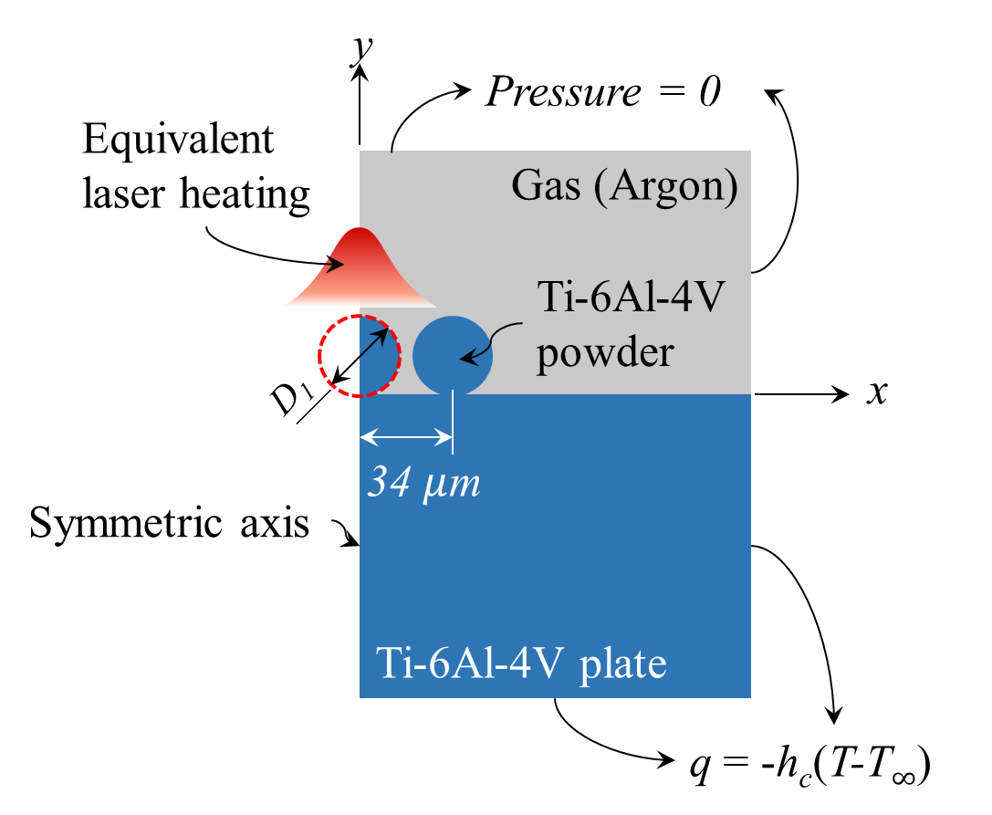
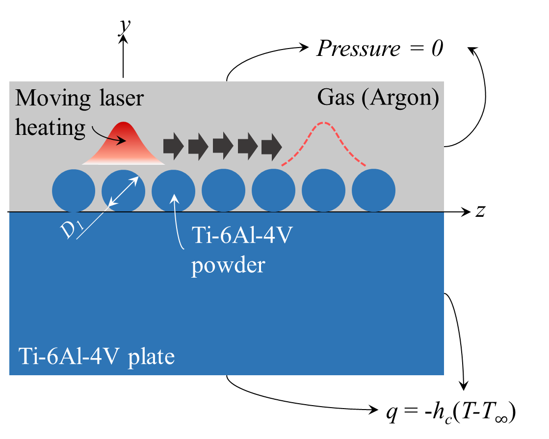
Figure 1. 2D Models of selective laser melting of powder bed.
For a consecutive line-by-line scanning, the process result is, except for the region near the surrounding boundary of the substrate, independent of x and z after the entire xz plane is scanned. Thus, the cross-section profile of the SLM part at a location x can be simulated using another simplified 2D model II shown in Fig. 1(b). For simplicity, only seven powders are considered here. In both models, the sizes of and distance between powder particles are arranged based on the normal packing of powder feedstock in a layer SLM process [25]. The analysed domains other than the powders and substrate are argon gas.
3.1. Level Set Function
When laser light impinges onto a material, the laser energy will be absorbed, depending on the value of material optical absorptivity. In this study, the laser energy absorption by the argon gas is not considered. Due to the fact that the optical penetration depth of metals is on the order of tens nanometers, about three orders smaller than the sizes of Ti6Al4V powders, it is reasonable to assume that the laser energy is only deposited on the surfaces of powder material. Once the powders absorb the laser energy, the temperature in the heated subsurface layer rapidly increases and then the thermal energy conducts into the surrounding region. Those parts of the powders will undergo a solid/liquid phase change when their temperature reaches the melting point and the liquid/vapor phase change when the temperature of liquid reaches the boiling point. The melt will flow down along the powder surface, wet with the adjacent powders, and consolidate. The dynamic outer contour of the melt must be traced since the laser energy will be deposited onto the surfaces of the melt (and the solid powders) that are directly exposed to the laser beam. In this work, the liquid/gas interface is tracked using a level set method [28, 29]:
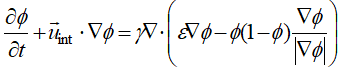
where f is the level set function,
![]() is the velocity of fluid mixture in the thin
layer of interface of thickness e, and g is the speed
of re-initialization. The value of f is set to be one (1) in the argon gas region
and -1 in the region of liquid, and smoothly varies from 1 to -1 over the layer
of mixture. The interface is determined by the zero-level set of the function f. The
interface velocity in the above equation is expressed as [30]:
is the velocity of fluid mixture in the thin
layer of interface of thickness e, and g is the speed
of re-initialization. The value of f is set to be one (1) in the argon gas region
and -1 in the region of liquid, and smoothly varies from 1 to -1 over the layer
of mixture. The interface is determined by the zero-level set of the function f. The
interface velocity in the above equation is expressed as [30]:
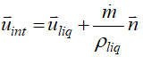
where ![]() is the normal vector of the
interface, and
is the normal vector of the
interface, and ![]() is the local mass flux of evaporation
described by
is the local mass flux of evaporation
described by
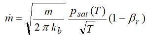
in which m is atomic weight of the liquid, kb Boltzmann constant, psat saturated vapor pressure, T is temperature, and βr the retrodiffusion coefficient which is assumed to be zero in this work. The saturated vapor pressure in Eq. (3) is given as:
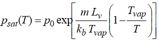
where po is 101,325 Pa, Lv is the latent heat of evaporation, and Tvap is the boiling point.
3.2. Governing Equations
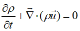
Depending on the occurrence of melting and vaporization, three phases of solid, liquid and vapor could appear in an SLM process. The responses of the three phases are different and should be solved using different models. Nevertheless, the physics of each phase can be described by the conservation equations of mass, momentum and energy though the forms are different. By removing the unneeded equations and/or terms from the three equations for a particular phase, a general mathematical model of heat transfer and fluid dynamics can be expressed as follows [31-36]:
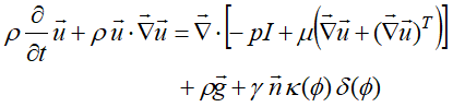
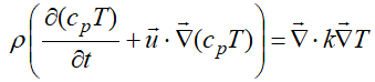
In
the above equations, r is mass density, p pressure, I
identity matrix, m dynamic viscosity, (.)T transposed matrix, ![]() gravity, g surface tension
coefficient,
gravity, g surface tension
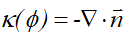
coefficient, ![]() surface normal vector, k surface
curvature, d(f) delta
function of the level set value, cp specific heat, T temperature, and k thermal
conductivity. The Marangoni effect is neglected here,
and the surface tension coefficient is assumed to be constant. For
simplicity, the solid/liquid phase transformation is modelled by including the
latent heat of fusion to the heat capacity of the powders. The thermal
properties of the mixture in the thin layer of interface vary smoothly over the
thickness by assuming the following relations:
surface normal vector, k surface
curvature, d(f) delta
function of the level set value, cp specific heat, T temperature, and k thermal
conductivity. The Marangoni effect is neglected here,
and the surface tension coefficient is assumed to be constant. For
simplicity, the solid/liquid phase transformation is modelled by including the
latent heat of fusion to the heat capacity of the powders. The thermal
properties of the mixture in the thin layer of interface vary smoothly over the
thickness by assuming the following relations:
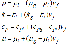
where vf
= (1+f)/2 is the
volume fraction of the liquid. The normal vector ![]() and curvature
and curvature ![]() of the interface in Eq. (6) can be determined from
the level set function
of the interface in Eq. (6) can be determined from
the level set function

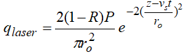
Since the laser energy is assumed to be absorbed only at the surfaces of melted and un-melted powders, the laser heat flux qlaser for the 2D model I in Fig. 1(a) is derived from a line-scanning Gaussian laser beam
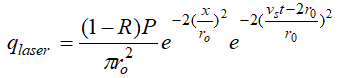
where R is the surface reflectivity; ro is the radius of laser spot on the powder bed. For the 2D model II in Fig. 1(b), the moving laser heat flux is given as:
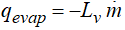
The thermal boundary condition at the interfaces between the solid powders and gas and between the melted metal and gas that includes laser energy flux, heat loss due to vaporization from the melted powder(s) if occurs, and the heat loss from radiation and convection becomes
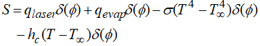
where σ denotes the Stefan-Boltzmann’s constant, hc is the heat transfer coefficient, and T∞is the surrounding temperature. The energy loss qevap from vaporization is estimated using the recondensation rate in the Knudsen jump [37].
In the beginning of laser process, the powders are solid. They could be melted partially or completely, and a small amount of material could be vaporized. In the numerical analysis of the solid part of powders, the convection term in the heat conduction equation (7) is removed and the mass continuity equation (5) and Navier-Stokes equations (6) are not needed. For the argon gas, the terms of thermal expansion and surface tension on the right-hand side of Eq. (6) are dropped off. The geometric level set method is mainly used to track the liquid-gas interface. The movement of the interface is realized by advecting the f variable using the velocity field calculation. Across the interface, the f varies progressively with a smooth step function, in addition to the properties variation from a phase to the other. The aforementioned heat transfer equation, the fluid partial differential equations, and the level set equation are simultaneously solved using the fully coupled solver in COMSOL Multyphysics®.
4. Experiment
To validate the simulation results, an SLM experiment was performed to measure the cross-section shapes and the heights of the re-solidified parts. The Ti6Al4V powders of average diameter 30 μm with purity exceeding 99.95% were spread on a titanium substrate. The experiment was carried out with the EOSINT M270 laser melting machine. The source of radiation is a CW fiber laser of maximum power 200 W, wavelength 1,070 nm, and spot size (ro) 35 μm. The maximum laser scanning speed can be up to 7.0 m/s. In this experiment, a single fusion line was produced by the laser beam at power 175 W. Three scanning speeds of 1,650 mm/s, 1,250 mm/s and 850 mm/s were tested. The re-solidified profile of the molten track was measured with a 3D optical profiler (Plu 2300, Sensofar). The experiment was conducted at the Laser and Additive Manufacturing Technology Center, ITRI.
5. Results and Discussions
In the numerical analysis, the parameters of
material and laser beam are the same as those used in the experiment. The properties of
Ti6Al4V powders can be found in Boyer et al. [34]. The
properties of argon gas are: density (![]() ) = 0.1 kg.m-3, viscosity (
) = 0.1 kg.m-3, viscosity (![]() ) = 5
) = 5![]() 10-4 Pa.s, heat capacity (CPgas)
= 520 J.kg-1K-1, and thermal conductivity (kgas)
= 0.017 W.m-1K-1 [38]. Other properties used in the
simulation are: e
= 1
10-4 Pa.s, heat capacity (CPgas)
= 520 J.kg-1K-1, and thermal conductivity (kgas)
= 0.017 W.m-1K-1 [38]. Other properties used in the
simulation are: e
= 1![]() 10-6 , g = 1 m/s , R
= 0.55 , and hc =100 W/(m2.K) . The
convergence test was carried out with three different finite element meshes for
the case of Model I with the laser scanning speed of 1,250 mm/s. >In the
following simulations, the numbers of elements used are 9,605 for a powder and
6,036 for argon gas in the Model I, and 17,168 for each powder and 5,952 for argon
gas in the Model II. A backward, adaptive
time-stepping algorithm is employed to implement the time integration. The initial
and maximum timesteps are set at 1 ps and 1 ms
respectively for the momentum and energy equations. The accuracy tolerance
is controlled within 0.01%.
10-6 , g = 1 m/s , R
= 0.55 , and hc =100 W/(m2.K) . The
convergence test was carried out with three different finite element meshes for
the case of Model I with the laser scanning speed of 1,250 mm/s. >In the
following simulations, the numbers of elements used are 9,605 for a powder and
6,036 for argon gas in the Model I, and 17,168 for each powder and 5,952 for argon
gas in the Model II. A backward, adaptive
time-stepping algorithm is employed to implement the time integration. The initial
and maximum timesteps are set at 1 ps and 1 ms
respectively for the momentum and energy equations. The accuracy tolerance
is controlled within 0.01%.
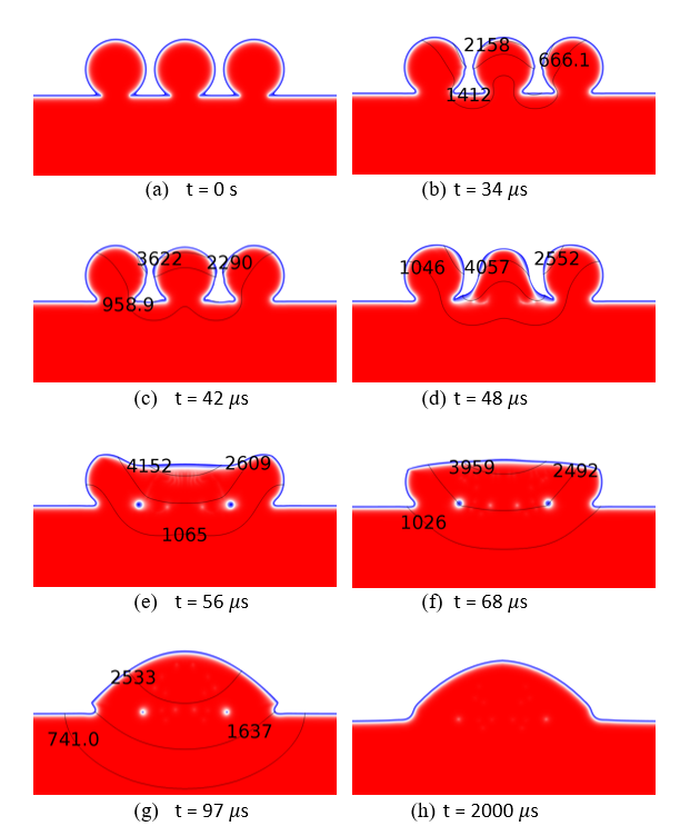
Figure 2 shows temporal evolution of the isotherm and geometry profile simulated for the model I, including melting of the metal powders, phase transformation from solid to liquid, melt flow, and re-solidification of the liquid phase. The laser scanning speed studied here is 1,250 mm/s. At t = 34 μs, the peak temperature has already exceeded the melting point (1,923 K). The central powder begins to melt from the top surface and soon lose its spherical shape (e.g., at 48 μs) because the gravity and surface tension act immediately to pull the newly liquefied material into the melt flow. After the melt of the central powder touches the boundaries of the melt of the central powder touches the boundaries of the two side powders, formation and dynamics of the melt pool can be observed (56 μs – 97 μs). All the powders achieve full melting at about 68 μs and then consolidate and finally form a semi-circular cylinder at about 97 μs. The effects of surface tension and gravity on the melt motion are manifest during this period of time. The maximum temperature in the field is found to be 4,152 K (the boiling point) shown at 56 μs and decreases to room temperature at about 2000 μs. It is interested in noting the different cross-section profiles at 56 μs and 2000 μs.
The vector distribution of velocity in the melt pool is shown in Fig. 3. The molten portion of the central powder accelerates downward by gravity and reaches the highest speed of about 7.26 m/s at 48 μs. After the melt reaches the the side powders, a great amount of the melt is quickly pulled, via surface tension, by the neighbor powders, leading to a bowl-shaped surface of the melt track. The gravity thus forces the melt to flow backward (t = 56 μs) and eventually form, together with the two completely molten side powders, a melt track of cylinder-like shape at about t = 97 μs.
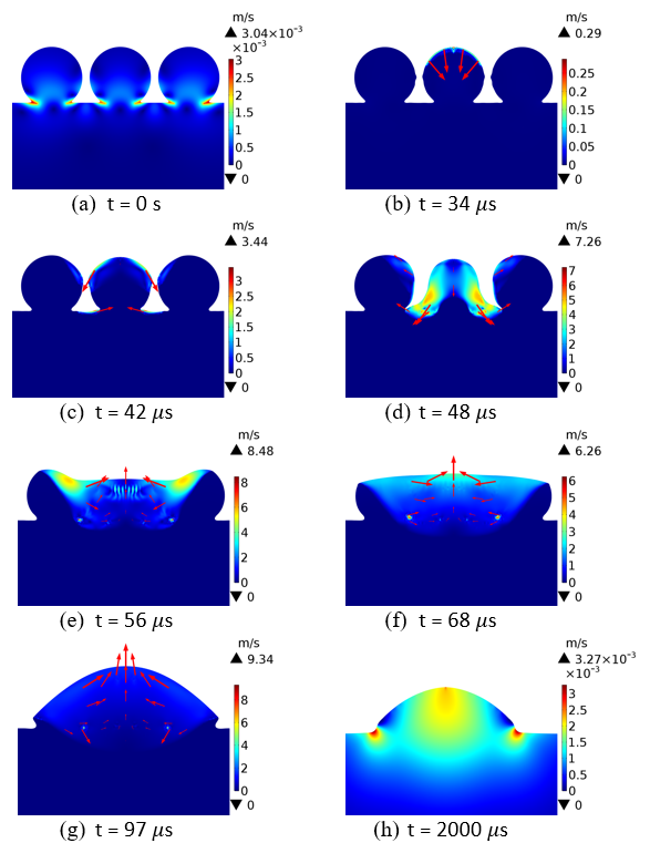
The evolution of the melt track is exhibited by the velocity vectors in Figs. 3(d)-3(g). The shape of the re-solidified part is displayed in Fig. 3(h) at t = 2000 ms. At this time, the velocity of the melt is almost zero since it is cooled to room temperature (Fig. 2(h)). It is noted that the small white spots shown in the figures are voids of gas.
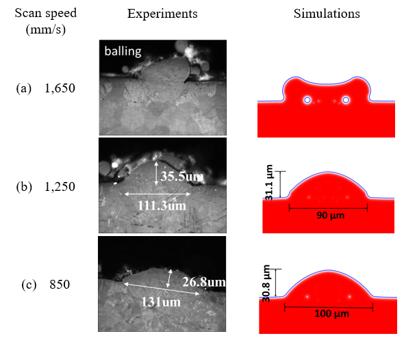
Figure 4 compares the experimental and numerical results of the final parts made by the three scanning speeds (1,650 mm/s, 1,250 mm/s and 850 mm/s). For the case of scanning speed 1,650 mm/s, the two side powders only melt in the region facing to the central one. The cross-section profile is quite different from the other two cases. However, the present simulations agree fairly well with the experimental results for the cases of the two slower scanning speeds. The simulated height and width are about 31.1 μm and 90 μm versus the experimental measurements 35.5 μm and 111.3 μm respectively for the scanning speed 1,250 mm/s, and about 30.8 μm and 100 μm versus 26.8 μm and 131 μm respectively for the 850 mm/s. No porosity is present in the consolidated parts. It is noted that due to the uncertainty of the laser and material parameters, the experimentally measured width and height of cross section of the melt pool could vary at different cross sections that are produced by laser scanning.
The balling effect was experimentally observed and explained by the Plateau-Rayleigh capillary instability of the melt pool [3, 39]. The result shown in Fig. 5 simulated with the scanning speed 2,050 mm/s may suggest the occurrence of balling. It is very likely that the final part could break into three separate pieces of powder size, similar to the experimental result shown in Fig. 4(a).
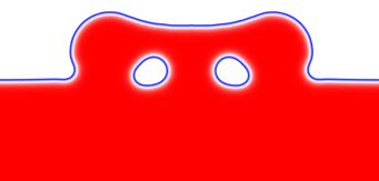
The conjectured breakages respectively start from the tops of the sizable voids and extend to the top surface of the part, caused by the intensified residual thermal stress in these regions during or after cooled down. This conjecture needs further stress and fracture analysis. The balling effect simulated here is due to insufficient time for the trapped air to escape out of the melt pool, not due to the Rayliegh instability. The undesired defects resulting from the balling include high surface roughness, discontinuous scan tracks, and/or broken parts. The ways to avoid balling are to (1) deposit sufficient laser energy by either increasing laser power or decreasing the scanning speed and/or (2) properly pack a dense powder bed. The improvement by decreasing the laser scanning speed is demonstrated as the results shown in Figs. 4(b) and 4(c).
For the model II, the simulated dynamic formation of the melt track is shown in Fig. 6, where the laser scanning speed is 1,250 mm/s. The laser beam is initially focused at z = 0, i.e., the tip-top of the second powder from left, moves to the right, and finally stops at the tip-top of the sixth powder. At t = 20 μs, the laser beam has travelled over 25 μm. The second powder is completely melted and the third one is under melting at this time. The melt of the second powder has arrived at and adhered to the two adjacent powders (see Figs. 6(a)). It can be seen from Fig. 6(b) that the velocity vectors point away from the focused area of the laser beam. The velocity of the backward melt flow is higher than that of the forward flow since less material is molten ahead. This strong backward flow drives the melt up and along the right surface of the first powder. Apparently, a portion of the first powder also melt. According to Korner, et al. [21], the molten particles would be ejected vertically and backward if surface tension is ignored. In contrast, Fig. 6 shows here that with surface tension the newly molten portion merges almost immediately into the melt flow.At t = 100 ms, five powders have completely melted, see Figs. 6(c) and 6(d).
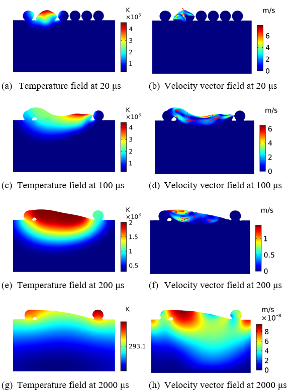
The
surface tension effect can be seen from the adhesion of the melt and formation of
the smooth top surface. At t = 100~200 ![]() s, the melt
on the top pool flows leftward while the melt in the bottom flows rightward (Figs.
6(d) & (f)). The resulting large contact area with the substrate leads to a
faster heat transfer that makes cooling down of the melt track faster than that
no surface tension is acting [27].
s, the melt
on the top pool flows leftward while the melt in the bottom flows rightward (Figs.
6(d) & (f)). The resulting large contact area with the substrate leads to a
faster heat transfer that makes cooling down of the melt track faster than that
no surface tension is acting [27].
The simulated consolidated track at t = 2000
![]() s can be seen
in Figs. 6(g) and 6(h), where the melt cools down to room temperature. The
average height of the final part is about ∼20
s can be seen
in Figs. 6(g) and 6(h), where the melt cools down to room temperature. The
average height of the final part is about ∼20![]() m, which is in a good correlation with the data [27]. Generally
speaking, the compact layer has a realistic height of around 67% of the powder
layer as observed in experiment and estimated from the powder packing density.
Unlike the simulation result shown in Fig. 4, no air void is simulated for this
scanning speed except the one close to the first powder.
m, which is in a good correlation with the data [27]. Generally
speaking, the compact layer has a realistic height of around 67% of the powder
layer as observed in experiment and estimated from the powder packing density.
Unlike the simulation result shown in Fig. 4, no air void is simulated for this
scanning speed except the one close to the first powder.
5. Conclusions
A 2D finite element model of multiphase fields is proposed to investigate the SLM of metal powders for AM, based on the conservation equations of mass, momentum and energy, along with multiple physics of solid/liquid and liquid/vapor phase changes, vapor pressure, gravity, surface tension, melt motion, wetting of powder particles with melt, and re-solidification. To deposit the laser energy, the liquid/gas interface is tracked using a level set method. All the equation and physics are coupled and solved simultaneously in COMSOL Multyphysics®. The simulations of the cross-section shapes of the re-solidified parts by a single line laser scanning and the heights of a single layer by adjacent line-by-line laser scanning are compared with the experimental measurements for Ti6Al4V powders. The present simulation clearly shows that air voids in a re-solidified parts can be removed by slowing down the laser beam scanning speed. In addition, the good correlations of the present two models with the experiments suggest that the present approach can achieve realistic results for the SLM process of metal powders. Further investigation of residual deformation and thermal stress induced in an AM part is suggested.
References
[1] G. N. Levy, “The role and future of the laser technology in the additive manufacturing environment,” Physics Procedia, vol. 5, pp. 65-80, 2010. View Article
[2] J. P. Kruth, “Material increase manufacturing by rapid prototyping techniques,” CIRP Annals - Manufacturing Technology, vol. 40, no. 2, pp. 603- 614, 1991.
[3] J. P. Kruth, L. Froven, V. J. Vaerenbergh, P. Mercelis, M. Rombouts, and B. Lauwers, “Selective laser melting of iron-based powder,” Journal of Materials Processing Technology, vol. 149, no. 1-3, pp. 616- 622, 2004. View Article
[4] B. Vrancken, L. Thijs, J. P. Kruth, and J. V. Humbeeck, “Heat treatment of ti6Al4V produced by selective laser melting: microstructure and mechanical properties,” Journal of Alloys and Compounds, vol. 541, no. 15, pp. 177-185, 2012. View Article
[5] W. M. Steen, Laser Material Processing. Berlin, Springer-Verlag Press, 2003.
[6] X. F. Shen, Y. Wang, J. Yao, and J. L. Yang, “Finite element simulation of thermal distribution in direct metal laser multi-track sintering,” Journal of Sichuan University, vol. 37, no. 1, pp. 47-51, 2005.
[7] I. A. Roberts, “Investigation of residual stresses in the laser melting of metal powders in additive laser manufacturing,” Ph.D. dissertation, University of Wolverhampton, 2012.
[8] P. Mercelis, and J. P. Kruth, “Residual stresses in selective laser sintering and selective laser melting,” Rapid Prototyping Journal, vol. 12, no. 5, pp. 254- 265, 2006.
[9] D. Karalekas, and D. Rapti, “Investigation of the processing dependence of SL solidification residual stresses,” Rapid Prototyping Journal, vol. 8, no. 4, pp. 243-247, 2002. View Article
[10] S. Koric, and B. G. Thomas, “Thermo-mechanical models of steel solidification based on two elastic visco-plastic constitutive laws,” Journal of Materials Processing Technology, vol. 197, no. 1-3, pp. 408- 418, 2008. View Article
[11] J. P. Kruth, J. Deckers, E. Yasa, and R. Wauthle, “Assessing and comparing influencing factors of residual stresses in selective laser melting using a novel analysis method,” Proceedings of the Institution of Mechanical Engineers, Part B: Journal of Engineering Manufacture, vol. 226, no. 6, pp. 980- 991, 2012. View Article
[12] J. L. Beuth, and N. W. Klingbeil, “Residual stressdriven delamination in deposited multi-layers,” International Journal of Solids and Structures, vol. 33, no. 1, pp. 65-78, 1996. View Article
[13] I. Yadroitsev, P. Bertrand, and I. Smurov, “Parametric analysis of the selective laser melting process,” Applied Surface Science, vol. 253, no. 19, pp. 8064- 8069, 2007. View Article
[14] E. Yasa, J. P. Kruth, and J. Deckers, “Manufacturing by combining selective laser melting and selective laser erosion/ laser re-melting,” CIRP Annals - Manufacturing Technology, vol. 60, no. 1, pp. 263- 266, 2011. View Article
[15] M. Shiomi, K. Osakada, K. Nakamur, T. Yamashita, and F. Abe, “Residual stress within metallic model made by selective laser melting process,” CIRP Annals - Manufacturing Technology, vol. 53, no. 1, pp. 195-198, 2004. View Article
[16] B. Vrancken, V. Cain, R. Knutsen, and J. V. Humbeeck, “Residual stress via the contour method in compact tension specimens produced via selective laser melting,” Scripta Materialia, vol. 87, no. 15, pp. 29-32, 2014. View Article
[17] C. Casavola, S. L. Campanelli, and C. Pappalettere, “Preliminary investigation on distribution of residual stress generated by the selective laser melting Process,” The Journal of Strain Analysis for Engineering Design, vol. 44, no. 1, pp. 93-104, 2009. View Article
[18] L. Papadakis, A. Loizou, J. Risse, and J. Schrage, “Numerical Computation of Component Shape Distortion Manufactured by Selective Laser Melting,” Procedia CIRP, vol. 18, pp. 90-95, 2014.
[19] S. Das, “Physical aspects of process control in selective laser sintering of metals,” Advanced Engineering Materials, vol. 5, no. 10, pp, 701-711, 2003. View Article
[20] E. Attar, “Simulation of selective electron beam melting processes,” Ph.D. dissertation, Universitat Erlangen-Nuremberg, 2011.
[21] G. Korner, E. Attar, P. Heinl, “Mesoscopic simulation of selective beam melting processes,” Journal of Materials Processing Technology, vol. 211, pp. 978- 987, 211.
[22] S. Kolossov, E. Boillat, R. Glardon, P. Fischer, and M. Locher, “3D FE simulation for temperature evolution in the selective laser sintering process,” International Journal of Machine Tools and Manufacture, vol. 44, no. 2-3, pp. 117-123, 2004. View Article
[23] B. Xiao, and Y. Zhang, “Laser sintering of metal powders on top of sintered layers under multiple-line laser scanning,” Journal of Physics D: Applied Physics, vol. 40, 6725-6734, 2007.
[24] B. Xiao and Y. Zhang, “Analysis of melting of alloy powder bed with constant heat flux,” International Journal of Heat and Mass Transfer, vol. 50, no. 11- 12, pp. 2161-2169, 2007. View Article
[25] W. J. Sames, F. A. List, S. Pannala, R. R. Dehoff, and S. S. Babu, “The Metallurgy and Processing Science of Metal Additive Manufacturing,” International Materials Reviews, vol. 61, no. 5, 315-360, 2016. View Article
[26] B. Schoinochoritis, D. Chantzis, and K. Salonitis, “Simulation of metallic powder bed additive manufacturing processes with the finite element method: A critical review,” Proceedings of the Institution of Mechanical Engineers Part B Journal of Engineering Manufacture, vol. 231, no. 1, pp. 1-22, 2015.
[27] W. King, A. T. Anderson, R. M. Ferencz, N. E. Hodge, C. Kamath, and S. A. Khairallah, “Overview of modelling and simulation of metal powder–bed fusion process at Lawrence Livermore National Laboratory,” Materials Science and Technology, vol. 31, no. 8, pp. 957-968, 2015. View Article
[28] H. Ki., P. S. Mohanty, and J. Mazumder, “A numerical method for multi-phase incompressible thermal flows with solid-liquid and liquid-vapor phase transformation,” Numerical Heat Transfer, Part B: Fundamentals, vol. 48, no. 2, pp. 125-145, 2005. View Article
[29] E. Olsson and G. Kreiss, “A Conservative Level Set Method for Two Phase Flow,” Journal of Computational Physics, vol. 210, no. 20, pp. 225-246, 2005. View Article
[30] G. Huber, S. Tanguy, M. Sagan, and C. Colin, “Direct numerical simulation of nucleate pool boiling at large microscopic contact angle and moderate Jakob number,” International Journal of Heat and Mass Transfer, vol. 113, pp. 662-682, 2017. View Article
[31] M. O. Bristeau, R. Glowinski, and J. Periaux, “Numerical methods for the Navier-Stokes equations. Applications to the simulation of compressible and incompressible viscous flows,” Computer Physics Reports, vol. 6, no. 1-6, pp. 73-187, 1987.
[32] J. M. Dowden, The Mathematics of Thermal Modeling: An Introduction to the Theory of Laser Material Processing. Chapman & Hall/CRC, Boca Raton Press, 2001.
[33] K. C. Mills, Recommended Values of Thermophysical Properties for Selected Commercial Alloys. Woodhead Publishing Ltd, Cambridge Press, 2002.
[34] R. Boyer, G. Welsch, and E. W. Collings, Materials properties handbook: titanium alloys. ASM International, Materials Park OH Press, 1994.
[35] Z. Fan and F. Liou, “Numerical modeling of the additive manufacturing (AM) processes of titanium alloy’ in ‘Titanium alloys – towards achieving enhanced properties for diversified applications,” A. K. M. N. Amin eds, pp. 3–28, 2012, Rijeka, Croatia. View Article
[36] J. M. Dowden, The Theory of Laser Materials Processing: Heat and Mass Transfer in Modern Technology, Springer, Wiesbaden Press, 2009.
[37] C. J. Knight, “Theoretical Modeling of Rapid Surface Vaporization with Back Pressure,” American Institute of Aeronautics and Astronautics Journal, vol. 17 no. 5, pp. 519-523, 1979.View Article
[38] C. Touvery, V. Bruyere, and P. Namy, “Comparison between phase field and ALE methods to model the keyhole digging during spot laser welding,” Proceedings of the 2013 Comsol Conference, Rotterdam, Rotterdam, Netherland, September 2006, pp. 1-7.
[39] I. Yadroitsev, A. Gusarov, I. Yadroitsava, and I. Smurov, “Single track formation in selective laser melting of metal powders,” Journal of Materials Processing Technology, vol. 210, no. 12, pp. 1624– 1631, 2010. View Article