Journal of Fluid Flow, Heat and Mass Transfer (JFFHMT)
ISSN: 2368-6111

Volume 5 - Year 2018 - Pages 78-86
DOI: 10.11159/jffhmt.2018.008
A CFD and Experimental Investigation of Slag Eye in Gas Stirred Ladle
Eshwar Kumar Ramasetti, Ville-Valtteri Visuri, Petri Sulasalmi, Timo Fabritius
University of Oulu, Process Metallurgy Research Unit
PO 4300, 90014 University of Oulu, Oulu
eshwar.ramasetti@oulu.fi; ville-valtteri.visuri@oulu.fi; petri.sulaslami@oulu.fi; timo.fabritius@oulu.fi
Abstract - In ladle metallurgy, gas stirring and behavior of the slag layer are very important for the quality of the steel. When gas is injected through a nozzle located at the bottom of the ladle into the metal bath, the gas jet exiting the nozzle breaks up into gas bubbles. The rising bubbles break the slag layer and create a slag eye. In this paper, the behavior of the slag eye area for different gas flow rates is been investigated through experimental measurements and CFD simulations. A 1/5-scale water model of 150 ton-ladle was deployed for the experimental measurements and for studying the effect of gas flow rate on the slag eye diameter. The physical modelling results show that the slag eye area changes from 20 to 182 cm2 when the gas flow rate increases from 1.5 to 15 NL/min. The dimensionless area of the open eye was found to be in agreement with earlier studies. The simulations were carried out in the commercial CFD code ANSYS Fluent with mesh generation in ANSYS Workbench. The numerical model developed is based on the Eulerian Multiphase Volume of Fluid (VOF) approach and employs standard 𝑘 − 𝜀 turbulence model for solving the turbulent liquid flow induced by bubble-liquid interaction. The simulation results of slag eye area showed a good agreement when compared to experimental results measured.
Keywords: CFD, ladle metallurgy, slag layer, multi-phase flows, Volume of Fluid (VOF) model.
© Copyright 2018 Authors - This is an Open Access article published under the Creative Commons Attribution License terms Creative Commons Attribution License terms. Unrestricted use, distribution, and reproduction in any medium are permitted, provided the original work is properly cited.
Date Received: 2018-07-11
Date Accepted: 2018-09-17
Date Published: 2018-12-20
Nomenclature
- r density (kg/m3)
- u fluid velocity (m/s)
- m effective viscosity (Pa∙s)
- g gravitational acceleration (m/s2)
- P pressure (Pa)
 effective turbulent viscosity (Pa∙s)
- k turbulent kinetic energy (m2/s2)
- e turbulent dissipation rate (m2/s3)
 turbulent eddy viscosity (Pa∙s)
 additional force vector (kg/(m2
s2))
additional force vector (kg/(m2
s2)) phase volume fraction (-)
- R production term
1. Introduction
In secondary metallurgy, gas stirring is extensively used for removal of inclusions, homogenization of chemical composition and desulphurization. The behavior of the slag layer plays an important role in refining the liquid steel as the efficiency of metal-slag reactions depend on the interaction between slag and steel created by gas stirring during the production process.
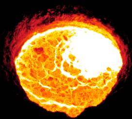
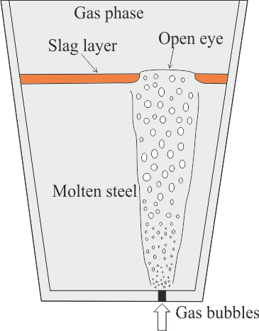
To boost the interaction between steel and slag, and to stimulate the desulphurization reaction, gas is injected to the molten steel through the porous plug located at bottom of ladle. The bubbles formed due to the gas injection in the column rises and infringes the slag layer forming slag eye. The slag eye formation in an industrial ladle in shown in Figure 1. Figure 2 presents a schematic illustration of the gas-stirring process in a ladle. The investigation of the three-phase flows associated in this process is very important for the production of steel [1].
2. Related Work
Over the years, many experimental measurements have been conducted to study the flow analysis, open eye formation and mixing time in the gas stirred ladle [2-6]. Wu et al. (7) measured the open size in a 1/5-scale water model of a 170-t steel ladle. Water and silicone oil were employed for modelling liquid steel and slag, respectively. Experimental measurements were conducted to study the effect of oil viscosities and gas flow rate on the open-eye size in the ladle. The results showed that the open-eye size increased with an increase in the gas flow rate, while oil viscosities had only a minor effect on the open-eye size. Krishapisharody et al. (8) performed measurements for slag open eye using a 1/10-scale model of a steel ladle. The measurements were conducted for three different bath heights and range of slag layer thickness heights. The results showed the size of the open eye increases with increase in the gas flow rate and decreases as the slag layer thickness increases. Liu et al. (9) measured slag eye area in a water model for different gas flow rates, slag layer thickness and porous plug locations.
Several
numerical simulation models [10-13] have been proposed for investigating the
fluid flow and mixing phenomena in gas stirred ladles. Mazumdar et al. (14)
made an extensive review of physical modelling, combined physical and
mathematical modelling and mathematical modelling studies. Liu et al. (15)
investigated the fluid flow and steel/slag/air interface behavior in argon
stirred ladle through numerical simulations. The performed simulations were
based on Eulerian Volume of Fluid (VOF) model and standard ![]() turbulence model with three different porous
plug configurations. The results showed that the flow pattern of the molten
steel is dependent on the plug configurations and gas flow rate.
Ramirez-Argaez (16) also performed the same kind of numerical work in
investigating the effect of gas flow rate, plug location and number of plugs on
the flow analysis in the ladle.
turbulence model with three different porous
plug configurations. The results showed that the flow pattern of the molten
steel is dependent on the plug configurations and gas flow rate.
Ramirez-Argaez (16) also performed the same kind of numerical work in
investigating the effect of gas flow rate, plug location and number of plugs on
the flow analysis in the ladle.
Recently, Li
et al. (17) used a Multiphase VOF model coupled with a population balance model
(PBM) and the RNG ![]() turbulence model to investigate the effect of
gas flow rate on the volume fraction of gas and bubble diameter in water model
ladle. Cloete et al. (18) did a similar kind work in studying the influence of
design variables on the flow analysis in full-scale gas stirred ladles with the
same approach used by Li et al. (17). On the other hand, there is little
quantitative information on the effect of gas flow rate on the slag eye
formation.
turbulence model to investigate the effect of
gas flow rate on the volume fraction of gas and bubble diameter in water model
ladle. Cloete et al. (18) did a similar kind work in studying the influence of
design variables on the flow analysis in full-scale gas stirred ladles with the
same approach used by Li et al. (17). On the other hand, there is little
quantitative information on the effect of gas flow rate on the slag eye
formation.
A comprehensive understanding of the effect of gas flow rate on the slag eye is a crucial requirement for today’s steel industry to produce high strength steels. The present study intends at attaining a better understanding of slag eye formation for different flow rates with eccentric single porous plug in a water model. The deployed water model is of 1/5 scale of 150- ton steelmaking ladle. The dimensionless area of slag eye relation with modified Froude number is been discussed and compared to the experimental data available in literature. For the numerical simulations, the VOF model is been used to track the slag eye behavior for different gas flow rates. The numerical simulation results of slag eye are validated to the experimental measurements measured.
3. Mathematical Modelling
A set of Navier-Stokes equations is solved for the liquid phase and a discrete-phase model is used for the gas phase. The continuity and momentum equations of the liquid phase are defined by Eqs. 1 and 2, respectively. A more detailed description of Eqs. 1 and 2 is available in the literature. (15-18).
where
![]() is the fluid velocity,
is the fluid velocity, ![]() is the
density,
is the
density, ![]() is the
pressure,
is the
pressure, ![]() is the effective turbulent viscosity, and
is the effective turbulent viscosity, and ![]() is the gravitational acceleration.
is the gravitational acceleration.
3. 1. Turbulent Equations
In this work,
the standard ![]() turbulence model was employed. The model solves
control equations for the turbulent kinetic energy and turbulent dissipation
rate, which are given by Eqs. 3 and 4, respectively.
turbulence model was employed. The model solves
control equations for the turbulent kinetic energy and turbulent dissipation
rate, which are given by Eqs. 3 and 4, respectively.


where
![]() is turbulent eddy viscosity,
is turbulent eddy viscosity, ![]() is the generation of turbulent kinetic energy
due to the mean velocity gradients as defined by Eq. 4, and
is the generation of turbulent kinetic energy
due to the mean velocity gradients as defined by Eq. 4, and ![]() and
and ![]() are empirical constants, which were set to
their default values
are empirical constants, which were set to
their default values![]() = 1.44 and
= 1.44 and ![]() = 1.92.
= 1.92.

3. 2. VOF Model
The VOF model is able to model two or more immiscible fluids by solving single set of momentum equations and tracking the volume fraction of each fluid throughout the domain. In this work, it is used to track the interfaces of liquid steel, slag and gas. The governing equation can be presented as follows:

where
![]() and
and ![]() represent the mass transfer from phase
represent the mass transfer from phase ![]() to
to ![]() and
and ![]() to
to ![]() in unit time
and volume;
in unit time
and volume; ![]() is the volume fraction of phase
is the volume fraction of phase ![]() and
and ![]() is the source term taken as 0 in fluent
software.
is the source term taken as 0 in fluent
software.
4. Experimental Details
In the present study, a one-fifth scale water model of 150-ton ladle was established to study the effect of stirring rate on the slag open eye area. A video camera was mounted on the top of the water model to monitor the development of the open eye. During the experiment, air was injected into the ladle through the nozzle located at bottom for stirring rates ranging from 1.5 to 15 NL/min. To simulate gas stirring in actual process, the water and oil were used respectively. The ImageJ software was used for measuring the slag open eye area. The details of the dimensions of water model ladle and material properties are shown in Table 1. All the physical properties are taken at temperature of 250 C.
5. Numerical Procedures
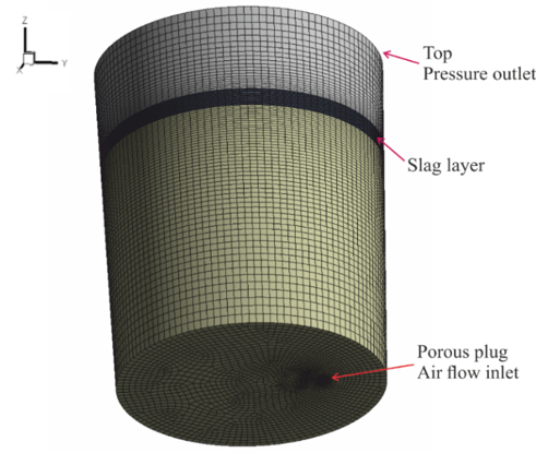
The simulations were carried out in the commercial code ANSYS Fluent software. The dimensions of the model are presented in Table 1. Trial calculations were conducted to study the mesh independency using different meshes with a total number of 229149, 488020 and 865130 cells. The error between the results of the slag eye area between 229149 and 488020 cells meshes was found to be approximately 5% and between 488020 and 865130 cells meshes was 2%. In taking consideration of the computational time, the optimum mesh with 488020 cells was selected for the simulations, which is shown in Figure 3.
Table 1. Parameters for both experiments and simulations.
| Parameters | Value |
| Bottom diameter of the ladle (mm) | 273.3 |
| Top diameter of the ladle (mm) | 298.4 |
| Height of the ladle (mm) | 755 |
| Water level depth in the ladle (mm) | 520 |
| Nozzle diameter (mm) | 8 |
| Slag layer thickness (mm) | 40 |
| Plug radial position | 0.54R |
| Density of water (kg/m3) | 997.2 |
| Dynamic viscosity of water (Pa∙s) | 0.000891 |
| Density of rapeseed oil (kg/m3) | 907.3 |
| Dynamic viscosity of oil (Pa∙s) | 0.0778 |
| Density of air (kg/m3) | 1.258 |
| Dynamic viscosity of air (Pa∙s) | 1.846 x 10 -5 |
At the inlet of the ladle, velocity inlet boundary condition with the gas flow rate in the range of 1.5 to 15 NL/min was used. At the top of the ladle, pressure outlet condition was sued, and no-slip boundary condition (velocity is zero near to the wall) was used to the ladle walls. The finite volume technique was used for the discretization of conservation equations and SIMPLE scheme is used for pressure-velocity coupling. The convergence criterion was set to be 10–6 and a variable time step is used by setting the Courant number to one. The data was collected when the flow reached steady state at around 20 sec.
6. Results and Discussion
It is very important to investigate the effect of gas flow rate on the slag eye opening as the efficiency of metal-slag reactions depend heavily on the interaction behavior between slag and steel created by gas stirring. The effect of gas flow rate on the slag open-eye area for 40 mm oil layer thickness was investigated experimentally. The experimental data measured of slag eye area is compared to the existing physical models available in the literature. Krishnapisharody and Irons (8) developed a mechanistic model for measuring the slag eye size for water model from fundamental fluid flow considerations. This model formulates the dimensionless area in terms of density ratio of the fluids and Froude number. The dimensionless area is expressed in terms of modified Froude number with the following correlation (8).
where ![]() is the density difference between water and
oil,
is the density difference between water and
oil, ![]() is the average plume rise velocity,
is the average plume rise velocity, ![]() is the slag eye area,
is the slag eye area, ![]() is the height of the water level depth and
is the height of the water level depth and ![]() /
/ ![]() is the densimetric Froude number.
is the densimetric Froude number.
Figure 4 indicates that dimensionless slag eye area obtained by the present water model may be somewhat higher when compared to the literature data. These measured experimental results of slag eye area were used for validating the numerical simulations.

and L&L = Li and Li (9).
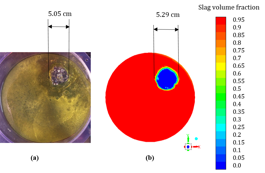
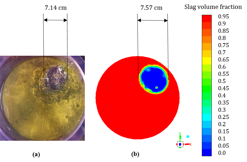
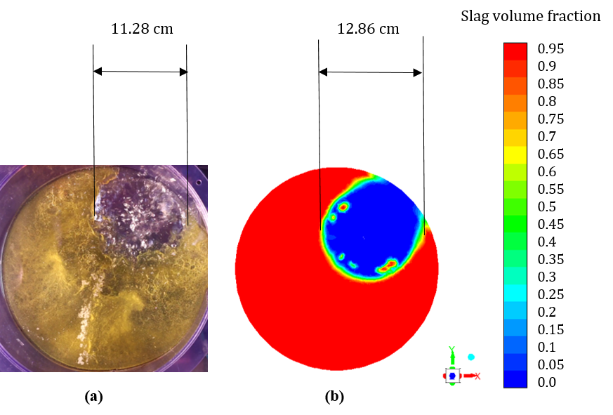
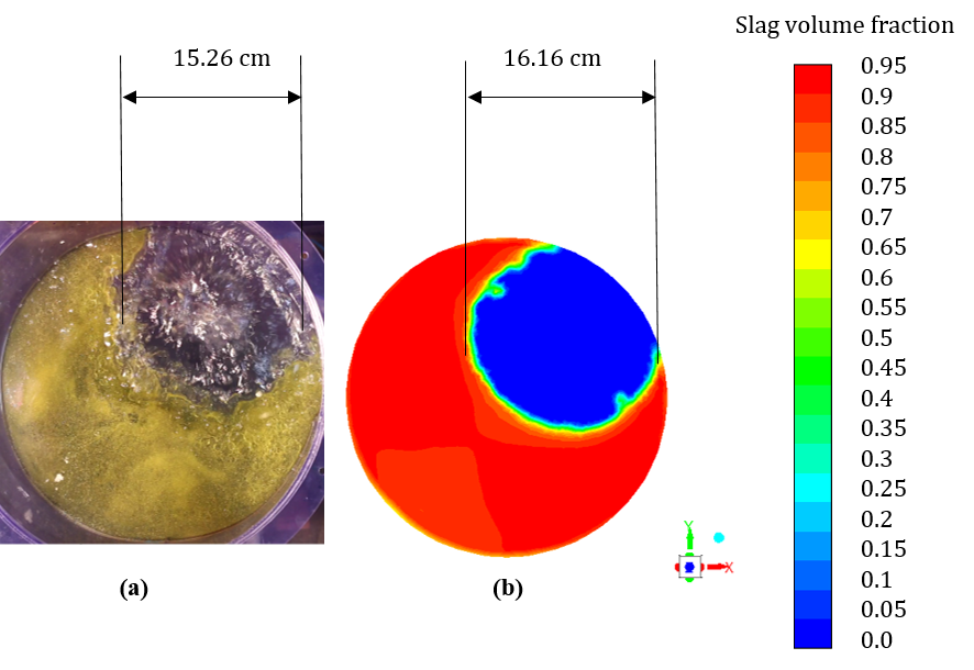
Figures 5 to 8 displays the comparison of increment of slag open-eye area of the experimental and simulation results. A smaller slag eye opening occurs when the flow rate of 1.5 NL/min is used, which is shown in Figure 5 and the slag open-eye formation was not observed to occur if the flow rate was lower than this. The flow rate of 1.5 NL/min generated a slag eye in diameter of approximately 5.05 cm in physical modelling, whereas 5.17 cm from simulation results. The diameter of slag open-eye expanded to 7.51 cm when flow rate elevated to 3.5 NL/min, which shows a good agreement to 7.14 cm measured experimentally (see Figure 6). When gas flow rate was increased to 7.5 NL/min, the diameter of slag open-eye enlarges to 11.28 cm, which was somewhat larger than this value obtained from the simulations (Figure 7). The slag open-eye expanded from 11.28 to 15.26 cm shown in Figure 7 when flow rate marked up to 15 NL/min, which was not quite agreeable with simulation result.
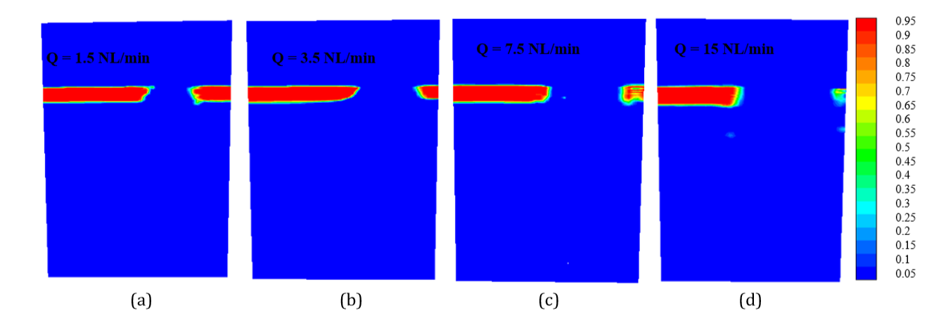
At high gas flow rates (7.5 and 15 NL/min), it was observed that there is significant deformation of slag layer during gas stirring, and the thickness of the slag layer becomes thin near the open eye. When the gas flow rate is increased beyond 15 NL/min, the open eye became highly dynamic and the fluid flow became more turbulent. The alteration of slag eye size with gas flow rate proves that the slag eye area increases with increase in gas flow rate, which can be seen in Figures 5 to 8 for both experiments and simulations. Figure 9 shows the effect of different gas flow rate on the deformation of slag layer shape at main section of the plug. It can be observed a smaller eye opening occurs when the gas flow rate of 1.5 NL/min was used and a bigger slag eye when gas flow rate of 15 NL/min was used.
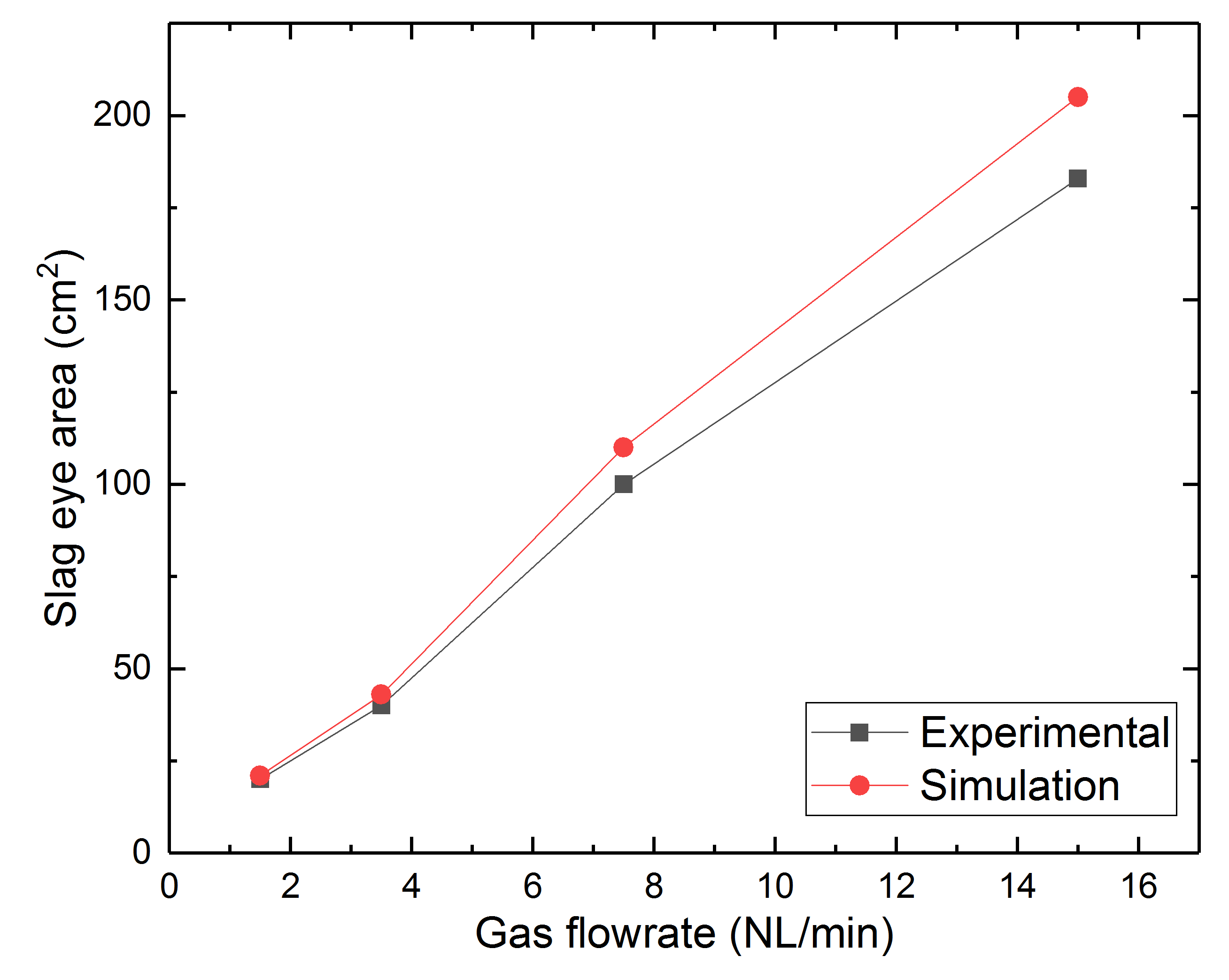
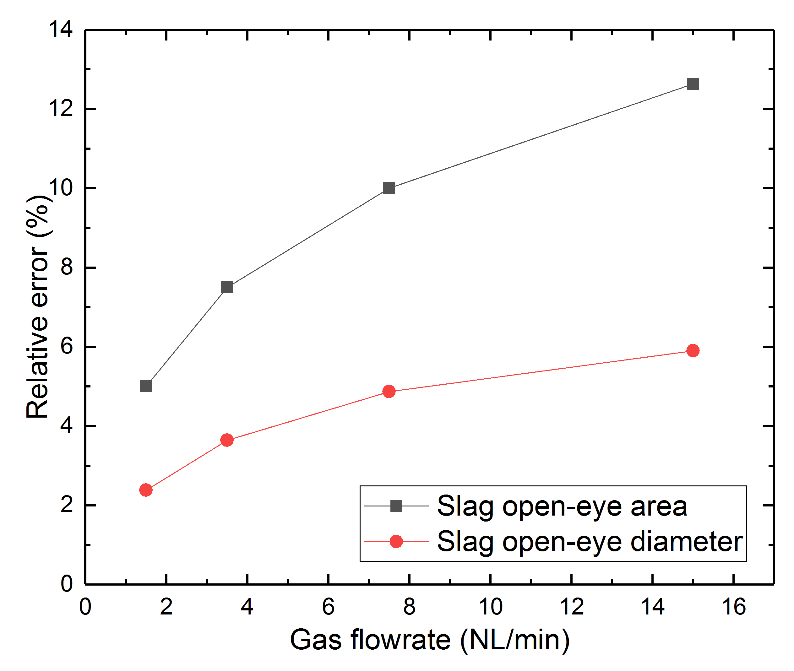
The increment in slag eye area when the gas flow rate is increased from 1.5 to 15 NL/min is displayed in Figure 10. The slag eye area increases from 20 to 182 cm2 for physical modelling and 21 to 205 cm2 for numerical simulations. The relative percentage error between the experimental and simulation results of slag eye area and diameter with the increase in the gas flow rate is depicted in Figure 11.
When the gas flow rate increased from 1.5 to 15 NL/min, the relative error in the area of the open eye increased from 5.0 to 12.6%, while the error in the open eye diameter increased from 2.4 to 5.9%. In view of the complexity of the studied case, the agreement is satisfactory. The present results of slag eye area in the water model are in qualitatively agreement with the experimental results of Li et al. (8) and simulations results of Liu et al. (15).
Over the past decade, there had been relatively few studies on both physical and CFD modelling together in studying the slag behavior in the ladle. In the current work, the simulations results are provided with strong experimental data measured for validation and vice versa. The present work represents a first step towards modelling an industrial ladle. At this stage, a numerical model was developed and a physical model was used for validation of the numerical approach employed. The results provide useful guidelines for the effect of gas flow rate and position of the open eye. In view of the results, the model appears to be appropriate for its purpose and can be modified for simulating a full-scale ladle. When ready, the model can be investigating the slag eye formation with increasing number of porous plugs, altering the porous plug diameter and slag layer thickness, thus providing useful information for optimizing the alloying and gas-stirring practice at steel plant.
7. Conclusions
A one-fifth scale water model is employed to study the effect of gas flow rate on the slag eye formations. A numerical model based on Multiphase Volume of Fluid (VOF) approach is developed to simulate the multiphase flow in the gas stirred ladle and validate the present experimental results of slag eye area. From the results, it was clear that the airflow injection rate has a significant effect on the area of slag open-eye. The slag eye area increases with increase in the gas flow rate for both experiments and simulations. The slag open eye predicted by the numerical model agreed well with experimental results. The present simulation results gives a better understanding of CFD in modelling the three-phase flows in steel making ladles.
Acknowledgements
The authors are grateful for financial support from the European Commission under grant number 675715-MIMESIS - H2020-MSCA-ITN-2015 that is part of the Marie Sklodowska-Curie Actions Innovative Training Networks European Industrial Doctorate Programme.
References
[1] B. Li, H. Yin, C. Q. Zhou and F. Tsukihashi, “Modelling of Three-phase Flows and Behavior of Slag/Steel Interface in an Argon Gas Stirred Ladle,” ISIJ International., vol. 48, no. 12, pp. 1704-1711, 2008. View Article
[2] Y. Xie and F. Oeters, “Experimental studies on the Flow Velocity of Molten Metals in a Ladle Model at Centric Gas Blowing,” Steel Research., vol. 63, no. 3, pp. 93-104, 1992. View Article
[3] J. Mandal, S. Patil, M. Madan and D. Mazumdar, “Mixing time and correlation for ladles stirred with dual porous plugs,” Metallurgical and Materials Transactions B., vol. 36, no. 4, pp. 479-487, 2005. View Article
[4] K. Yonezawa and K. Schwerdtfeger, “Spout Eyes Formed by an Emerging Gas Plume at the Surface of a Slag-Covered Metal Melt,” Metallurgical and Materials Transactions B., vol. 30, no. 413, pp. 763-772, 1999.
[5] D. Mazumdar and J.W. Evans, “A model for estimating exposed plume eye area in steel refining ladles covered with thin slag,” Metallurgical and Materials Transactions B., vol. 35, no. 39, pp. 400404, 2004. View Article
[6] K. Krishnapisharody and G. A. Irons, “An Extended Model for Slag Eye Size in Ladle Metallurgy,” ISIJ International., vol. 48, no. 12, pp. 1807-1809, 2008. View Article
[7] L. Wu, P. Valentin and D. Sichen, “Study of Open Eye formation in an Argon Stirred Ladle,” Steel Research International., vol. 81, no. 7, pp. 440-458, 2010. View Article
[8] K. Krishnapisharoday and G. A. Irons, “Modeling of Slag Eye Formation over a Metal Bath Due to Gas Bubbling,” Metallurgical and Materials Transactions B Research International., vol. 37B, no. 5, pp. 763-772, 2006. View Article
[9] Z. Liu, L. Li and B. Li, “Modeling of Gas-SteelSlag Three-Phase Flow in Ladle Metallurgy: Part 1. Physical Modeling,” ISIS International., vol. 57, no. 11, pp. 1971-1979, 2017. View Article
[10] S. Ganguly and S. Chakraborthy, “Numerical Investigation on Role of Bottom Gas Stirring in Controlling Thermal Stratification in Steel Ladles,” ISIS International., vol. 44, no. 3, pp. 537-546, 2004. View Article
[11] S. Ganguly and S. Chakraborthy, “Numerical modelling studies of flow and mixing phenomena in gas stirred steel ladles,” Ironmaking and Steelmaking., vol. 35, no. 7, pp. 524-530, 2008. View Article
[12] M. Warzecha, J. Jowsa, P. Warzecha, and H. Pfeifer, “Numerical and experimental investigations of steel mixing time in a 130-t ladle,” Steel Research International., vol. 79, no. 11, pp. 852-860, 2008. View Article
[13] J. F. Domgin, P. Gardin and M. Brunet and B. Li, “Experimental and numerical investigation of gas stirred ladles,” in Proceedings of the Second International Conference on CFD in the Minerals and Process Industries, Melbourne, Australia, 1999, vol. 35, no. 1, pp. 1-20.
[14] D. Mazumdar and R. I. L. Guthrie, “The Physical and Mathematical Modelling of Gas Stirred Ladle Systems,” ISIS International., vol. 35, no. 1, pp. 1-20, 1995. View Article
[15] H. Liu, Z. Qi and M. Xu, “Numerical Simulation of Fluid Flow and Interfacial Behaviour in Threephase Argon-Stirred Ladles with One Plug and Dual Plugs,” Steel Research International., vol. 82, no. 4, pp. 440-458, 2011. View Article
[16] M. A. Ramirez-Argaez, “Numerical Simulation of Fluid Flow and Mixing in Gas-Stirred Ladles,” Materials and Manufacturing Processes., vol. 23, pp. 59-68, 2007. View Article
[17] L. Li, Z. Liu, B. Li, H. Matsuura and F. Tsukihashi, “Water Model and CFD-PBM Coupled Model of Gas-Liquid-Slag Three-Phase Flow in Ladle Metallurgy,” ISIJ International., vol. 55, no. 7, pp. 1337-1346, 2015. View Article
[18] S. W. P. Cloete, J. J. Eksteen and S. M. Bradshaw, “A numerical modelling investigation into design variables influencing mixing efficiency in full scale gas stirred ladles,” Minerals Engineering., vol. 4647, pp. 16-24, 2013. View Article