Journal of Fluid Flow, Heat and Mass Transfer (JFFHMT)
ISSN: 2368-6111

Volume 5 - Year 2018 - Pages 71-77
DOI: 10.11159/jffhmt.2018.007
Numerical Simulation of Fluid Flow and Heat Transfer through Channels of Plate Heat Exchangers
Dragan Mandic
JKP Belgrade Power Plants
Savski nasip 11, Belgrade,Serbia
dragan.mandic@bgdel.rs
Abstract - The
subject of this paper is numerical simulation of fluid flow and heat transfer
in channels of plate heat exchangers for heating domestic hot water in heating
substations in Belgrade.
This paper puts a special
emphasis on numerical simulation of hydraulic parameters of fluid flow and heat
transfer parameters performed in the collective and individual channels of the
plate heat exchangers.
The geometric model of the
collective channel plate for the passage of fluid was obtained by connecting
all geometrical models of individual channels on the one exchanger plate.
The numerical network for
both geometric models was generated separately and the boundary conditions were
adopted for different fluid velocity through them.
The uneven distribution of
shear stresses on the plate of the heat exchanger was determined for various
speeds of fluid in the collective and individual channels for the fluid flow.
At the same time the fluid velocity in the collective channels had a value of
0.1m/sec, and an individual channels it was 0.01m/sec.
Shear stress values, obtained
by numerical simulation, were compared with the experimental results of these
stresses which were obtained by the measurement of the fluid parameters that
have approximately the same velocity (0.1m/sec).
Due to the
significant impact of the distribution and intensity of tangential stress on
the plate fouling on the area of the heat exchanger, these results can serve as
a basis for the introduction of new project procedures for the selection of
plate heat exchangers in district heating systems.
Keywords: Plate Heat Exchangers, Fluid Flow, Chanells.
© Copyright 2018 Authors - This is an Open Access article published under the Creative Commons Attribution License terms Creative Commons Attribution License terms. Unrestricted use, distribution, and reproduction in any medium are permitted, provided the original work is properly cited.
Date Received: 2018-01-04
Date Accepted: 2018-05-08
Date Published: 2018-10-25
Indices
Pa, N/m2, Pascal;
B, m, width;
b. m, the distance between plates;
L, m, length;
β,°, Corner of the globe;
δ, m, thickness;
 p,
Pa, is the pressure drop due to friction;
p,
Pa, is the pressure drop due to friction;b, m, is the distance between plates;
L, m, is the effective plate length;
τ, shear stress or sub-grid scale, molecular stress tensor ;
 ,
kg/m3,density;
,
kg/m3,density;- , kg/m, density;
 kg/m· sec, Additional Variable (non-reacting scalar);
 m3, volume;
 , kg/m·sec,
dynamic diffusivity of an Additional Variable;
, kg/m·sec,
dynamic diffusivity of an Additional Variable;A,m2, area;
 kg/m3·sec, mass source;
  m/sec, velocity magnitude;
Ttot,° Celsius, total temperature;
Tstat ,° Celsius, static temperature;
Tspec ,° Celsius, specified total temperature;
Cp, m2/s2 ∙°K, specific heat capacity at constant pressure;
Pabs, kg/m ∙sec2, absolute pressure;
Pstat, kg/m ∙sec2, static pressure;
Pref, kg/m ∙sec2, reference pressure;
ṁ, kg/sec, mass flow rate
Subscripts
pl, plate;
ef, effective;
tot,totaly;
spec, specified;
stat, static
ref, referent;
Inlet,inlet.
1. Introduction
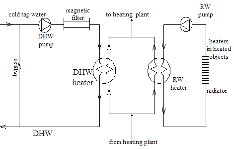
The domestic hot water (DHW) system is a part of the district heating system in Belgrade (Serbia). JKP Beogradske elektrane (municipal company for district heating in Belgrade) continuously improves the system by incorporating prefabricated compact substations which serve two purposes: heating water for the radiator heating system and heating of the DHW.
This paper will describe the influence of water velocity on the factor of fouling in plate heat exchangers, based on measurements on four district heating substations (DHS) in the Sector of the Heat Plant Zemun.
This paper, Numerical Simulation is applied to the individual plate heat exchanger for heating domestic hot water in a heat-transmitting substation for district heating, whose scheme is given in the following figure [1]:
1.1. Problem Statement
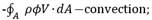
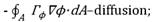
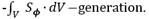
General conservation (transport) equations for mass, momentum, energy, species, etc. are solved on this set of control volumes[7]:

where:
- ![]() , kg/m3, density;
, kg/m3, density;
- ![]() kg/m· sec, Additional Variable (non-reacting scalar);
kg/m· sec, Additional Variable (non-reacting scalar);
- ![]() m3, volume;
m3, volume;
- ![]() m2, area;
m2, area;
- ![]() , kg/m·sec, dynamic diffusivity of an
, kg/m·sec, dynamic diffusivity of an
Additional Variable;
- ![]() kg/m3·sec, mass source;
kg/m3·sec, mass source;
-![]() caused by local fluctuations;
caused by local fluctuations;
- Partial differential equations are discretized into the system of algebraic equations;
- All algebraic equations are solved by numerical algorithms.
1.2. Shear Stress
In the past few decades, wall shear stress has become a significant parameter in fouling factor analysis, since it is a measure of the fluid stress along the face of the corrugated plate.
Wall shear stress is defined as follows[1]:

-
![]() p,
Pa, is the pressure drop due to friction;
p,
Pa, is the pressure drop due to friction;
-b, m, is the distance between plates;
-L, m, is the effective plate length.
2. Numerical Simulation
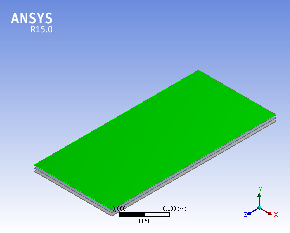
Numerical Simulation was done for flat-consolidated channels between the developed flat-panel and individual channels between the profiled plates. The heat transfer and fluid flow modeled for the flat plate heat exchanger, which has a total active surface area for the heat passage, is identical to the ruffle plate, from which the flat plate is obtained.
Collective channels to Fluid 1and Fluid 2 , among which is a developed flat-plate heat exchanger and plates with individual channels , are drawn in the three-dimensional software ANSYS Design Modeler, Figure No.2 and Figure No.3[2] [3] [4] .
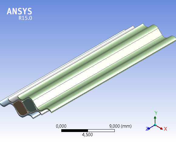
Therefore, all flow of fluid through the individual channels is taken as the aggregate (Fluid 1 and Fluid 2), and input and output cross-sections of a collection channel (for an aggregate of the fluid flow) are of the same length (119mm- length of flat plate heat exchanger) and a width of 0.96 mm. This represents the equivalent diameter or the width of the individual channel of plates, through which the fluids pass [8].
For collective channels the same flow rate of 0.1 m / sec is adopted for both fluids, which is the same rate as in individual channels [8]. This gives the collective channels the same boundary conditions as each channel individually.
In these individual channels, velocity of Fluid 1 and Fluid 2 are identical and amounts to 0.01 m / sec.
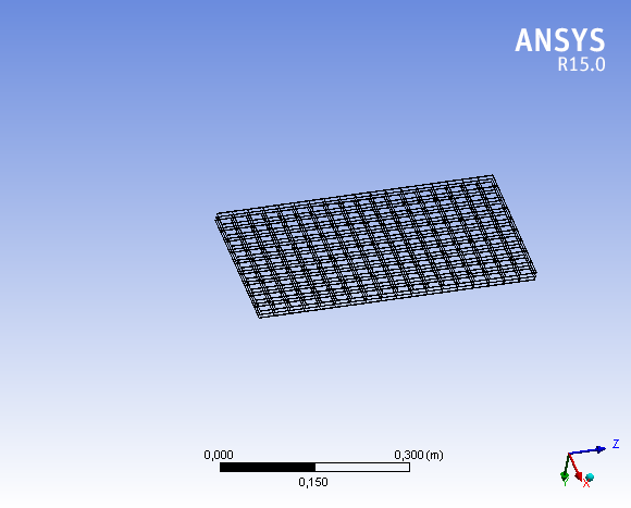
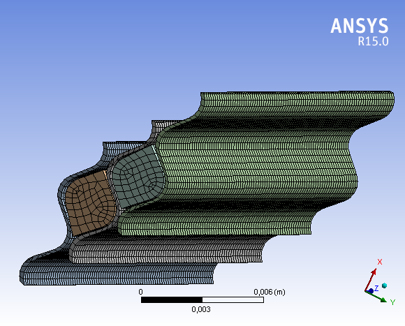
To create the computed parameters of the processes it is necessary to label all the surfaces for heat exchange and fluid movement that are needed for generating the numerical network.
Figure No.4 and Figure No.5 [5] [6].
The basic boundary conditions for exchange of heat and flow of fluid are as follows [1]:
1. FLUID 1- input, FLUID 2- input:
- Mass of fluid flow or fluid flow rate between the plates of exchangers during the heat exchange, for both fluids have an adopted value of 0.1 m/sec.
The mass influx is calculated using:

Where
![]() -is
the integrated boundary surface area at a given mesh resolution.
-is
the integrated boundary surface area at a given mesh resolution.
2. FLUID 2- input:
- Mean value of static pressure of 550, 000Pa.
The Reference Pressure (Eqn. 4) is the absolute pressure data from which all other pressure values are taken.

ANSYS CFX [7] solves for the
relative static pressure-![]() (thermo dynamic pressure)(Eqn.5) in the flow
field , and is related to Absolute Pressure-
(thermo dynamic pressure)(Eqn.5) in the flow
field , and is related to Absolute Pressure-![]() (Eqn.6):
(Eqn.6):

 +
+
3. The input temperature of the fluid during periods of heat exchange of 65 degrees Celsius for Fluid 1 and 50 degrees Celsius for heated Fluid 2.
The total Temperature, the boundary advection and diffusion terms for specified total temperature, are evaluated in exactly the same way as specified static temperature, except that the static temperature is dynamically computed from the definition of total temperature:

which for a fluid with constant heat capacity is:
The values of absolute pressure Fluid 1 are not treated as boundary conditions due to its variability and conditionality with the state of hydraulic parameters in other parts of the hydraulic system (hot water system).
This does not apply to the distribution of shear stresses and absolute pressure Fluid 2 due to the influence of the actual value of these stresses under the real working conditions.
For all designated board surfaces that exchange heat, it is possible to simulate the values of fluid flow, values of the projections of the velocities of fluid flow in the direction of all three axes and total energy exchanged, for a certain number of iterations- until these parameters become closer to their asymptotic values as shown in the following Figure No.6[8].

The input and output values of the vector velocity of the fluid in the collective channels of plate heat exchangers and the value of velocity vectors of Fluid 1 and of Fluid 2 along the individual channels of plate exchangers were shown in Figure No.7 and Figure No.8.
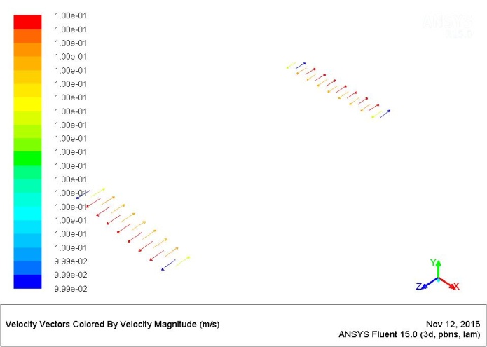
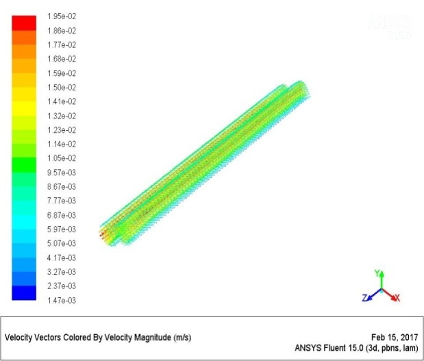
The diagram shows that the vectors of velocity have the highest intensity in the central parts of the input-output cross sections of channels and that the velocity is decreasing in the direction of the end points of these cross sections.
2.4. Numerical Simulation Post Processing
Within post processing modeling it is possible to change the relevant parameters such as flow rate, temperature, dynamic pressure and speed to display in an arbitrary number of intervals to complete the indicated numerical simulations in networked surfaces. It is significant that in the context of post processing research we can examine the value of tangential stress at the surfaces of exchangers that have a direct impact on the fouling of plates.
In this paper, processing modeling parameters is made for analysis of the exchange of heat and tangential stresses on the common surface between the plate heat exchangers and fluid.
2.4.1. Shear Stresses between the Surface of the Flat Plate Heat Exchangers and the Fluid in the Collective Channels
Within post processing research of shear stresses on the surfaces of plate heat exchangers, which have a direct impact on their contamination, used an absolute pressure of Fluid 2 of 520000Pa (at the exit from the exchanger) and an absolute pressure of Fluid 2 of 550000Pa (at the entrance of the exchanger). These pressures are the pressure levels of cold water that are added into the systemic circulation at the entrance to a heat exchanger to compensate water losses in the system due to sanitary needs in houses. It should be noted that the absolute value of the water pressure at entrance to the heat exchanger changed in the interval from 550000Pa to 520000P as a result of loss of water in the system that is consumed for sanitary purposes. When the value of this pressure falls below 520000Pa (due to loss of water) the system increases the level of absolute pressure to 550000Pa. Changes in levels of these pressures occur for a period from a few seconds to a fraction of a second and are directly proportional to the length of the interval of water consumption in homes.
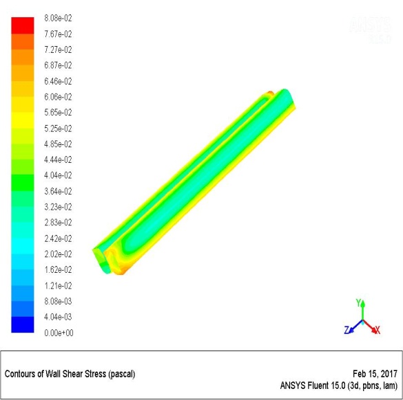
2.4.2. Shear Stresses between the Surface of the Ruffle Plate Heat Exchangers and the Fluid in Individual Channels
From the Figures below No. 9 and No. 10, we can see that the values of shear stresses in the individual channels of ruffle plate exchangers range from 0.0283 Pa to 0.0646 Pa. The boundary conditions for the calculation of these stresses were related to the speeds of flow in the channels of the plate. For Fluid 1 and Fluid 2 this speed has an estimated value of 0.01m/sec. It may be noted that the value of the stresses in the individual channels is about 100 times lower than in the collective channels of the plate heat exchangers. These results have been achieved for fluid flow at one tenth the speed in the individual channels (0.01m / sec) in relation to the speed of fluid flow in the channel of the flat plate (0.1m / sec.).
The following table[1] [8] shows the values of tangential stress on the plates of exchangers, which are calculated on the basis of the measured values of the parameters of fluid flow and which have been compared to the values of the stress obtained by numerical simulation:
Table 1. Experimental data and comparisons with CFD simulations-without inlet and outlet zones effect.
| Experiment number | 1 | 2 | 3 | 4 |
| Velocity,m/sec (measured value) |
0,109 | 0,107 | 0,105 | 0,108 |
| Wall shear stress correlation,Pa (S.Genic,D.Mandic et. al.2012) |
9,72 | 9,39 | 9,07 | 9,56 |
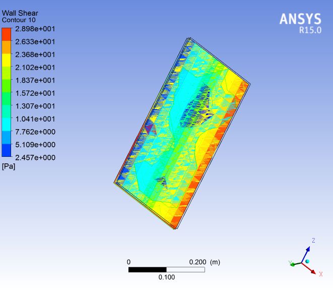
| Wall shear stress - in the assembly plate (CFD),Pa | 2,457-28,98 | |||
| Velocity (CFD), m/sec | 0,1 | |||
Table No.1 shows the experimental values of the tangential stress on the plates of exchanger (fluid flow at speeds of 0.105m / sec to 0,109m / sec) which differ substantially from the calculated values of the stress in the Numerical Simulation (for a constant velocity of 0.1 m / sec ).
In results of numerical simulation, on the surface of plates one can note the distribution with large differences of the intensity of the stress, that is not consistent with the character level, and changes of other parameters of heat exchange.
The uneven distribution of shear stresses is caused by great changes of the absolute level of water pressure at the entrance to the heat exchanger that occur in seconds which are the initial boundary conditions for the calculation of the parameters of heat exchange with numerical simulation. Great changes in water pressure cause enormous differences in intensity of the stress relative to the value obtained by the experimental method.
3. Conclusion
Based on the above, it can be said that the numerical simulations are fully applicable to practical research of parameters of fluid flow and heat delivery in plate heat exchangers.
Although the results of the numerical simulation of shear stresses on the plates of heat exchangers differ greatly from the experimental values of these stress (for almost the same value of fluid velocity), the numerical simulations pointed to an uneven distribution of these stresses on the exchangers plates.
On that basis, we can predict segments of the surface of the board with the possibility of intense contamination (compared to other segments of the surface of the plate) to the extent that endangers the process of exchanging heat.
The variable parameters in different technological processes make it difficult to predict project and budgetary procedures.
Using this model makes the optimization of these procedures possible, because it enables the application of variable operating parameters to predict lowering maintenance costs of technological processes.
In this case the numerical simulation model can predict the time of flow and temperature degradation. This analysis can be used to perform preventative maintenance on the heat exchanger plates to remove layers of fouling prior to the heat exchange plates being totally contaminated, not being able to be cleaned, and having to be replaced.
References
[1] S. B. Genić, B. M. Jaćimović, D. N. Mandić, D. Petrović, “Experimental determination of fouling factor on plate heat exchangers in district heating system,” Energy and Buildings, vol. 50, pp. 204- 211, 2012. View Article
[2] I. A. Stogiannisa, S. V. Paras, O. P. Arsenyevab, P. O. Kapustenkob, “CFD Modeling of Hydrodynamics and Heat Transfer in Channels of a PHE,” Chemical Engineering Transactions, vol. 35, 2013.
[3] Vinay Patil, Manjunath H., Basavaraj Kusammanavar, “Validation Of Plate Heat Exchanger Design Using CFD,” International Journal of Mechanical Engineering and Robotics Research, vol. 2, no. 4, 2013.
[4] M. V. Bhatia, P. N. Cheremisinoff, Heat Transfer Equipment. Technomic Publishing, Lancaster, 1980.
[5] H. Kumar, “The Plate Heat Exchanger: Construction and Design,” 1st National Conference on Heat Transfer, Leeds, 1984. View Article
[6] J. Kerner, “Plate heat exchangers: avoiding common misconceptions,” Chemical Engineering, vol. 116, no. 2, pp. 40–43, 2009.
[7] ANSYS Introduction to CFD Analysis, Introductory FLUENT Notes. FLUENT v6.3 2006.
[8] D. Mandic, “CFD modelling of hydrodynamic phenomena and heat transfer in channels of plate heat exchangers,” 4th International Conference of Fluid Flow, Heat and Mass Transfer (FFHMT’17), Toronto, Canada, 2017. View Article