Journal of Fluid Flow, Heat and Mass Transfer (JFFHMT)
ISSN: 2368-6111

Volume 11 - Year 2024 - Pages 29-35
DOI: 10.11159/jffhmt.2024.004
Optimal Control for Thermal Management of Li-ion Batteries via Temperature-Responsive Coolant Flow
Aaditya Sakrikar1, Jacob Thomas Sony 1, Pranav Singla 1, Aniruddh Baranwal 1
1Indian Institute of Technology Bombay
Department of Mechanical Engineering, IIT Bombay, Mumbai-400076, India
200100002@iitb.ac.in; 200100072@iitb.ac.in; 200040102@iitb.ac.in; 200100025@iitb.ac.in
Abstract - A Battery Thermal Management system (BTMS) is responsible for cooling, heating, insulation, and ventilation of the battery pack to ensure safe, reliable, and long-lasting operation of the battery pack under controlled optimal conditions. Cold plates are one of the most popular active thermal control methods used in BTMS. Most cold plate-based cooling strategies use a constant coolant flow rate. A possible method to improve this could be a temperature-responsive coolant flow strategy. This paper focuses on the optimal control of coolant flow for an active hydraulic BTMS with mini-channel cooling plates. An appropriate cost function was formulated to optimise the coolant flow, capturing the trade-off between thermal degradation and pumping power. A software framework was created to obtain the optimal solution for flow rate as a function of time. The results obtained after optimisation showed that an optimal cooling strategy for high heat dissipation generally has three phases - i) increasing flow rate, ii) saturated flow rate, and iii) decreasing flow rate, which gives a lesser cost when compared to a constant flow rate.
Keywords: Optimal control, BTMS, electric vehicles, cold plate, thermal degradation.
© Copyright 2024 Authors - This is an Open Access article published under the Creative Commons Attribution License terms Creative Commons Attribution License terms. Unrestricted use, distribution, and reproduction in any medium are permitted, provided the original work is properly cited.
Date Received: 2023-09-16
Date Revised: 2024-01-12
Date Accepted: 2024-02-02
Date Published: 2024-02-07
1. Introduction
Lithium-ion (Li-ion) batteries have become increasingly popular in recent years due to their long-life span, low maintenance requirements, and high reliability in various devices, including laptops, smartphones, and electric vehicles (EVs). An important component integrated with most Li-ion battery packs in EVs is the Battery Thermal Management System (BTMS) [1]. A BTMS is responsible for cooling, heating, insulation and ventilation of the battery pack to ensure safe, reliable and long-lasting operation of the battery pack under controlled optimal conditions. Cold plates are one of the most popular active thermal control methods used in BTMS [2]. Most cold plate-based cooling strategies use a constant coolant flow rate. The current literature has explored the topology optimization of the cold plate channels [3-4]. The effect of an oscillating flow was investigated by Li et al. [5] which showed that pulsating flow requires a lower pumping power when compared to constant flow rate cold plates for the same thermal performance. However, a temperature-based optimal coolant flow strategy hasn’t been explored in the literature. At lower system temperatures, the constant flow rate used is higher than the value required for maintaining the optimal temperature range of the batteries, resulting in higher pumping power. A possible method to improve this could be a temperature-responsive coolant flow strategy. This paper focuses on the optimal control of coolant flow for an active hydraulic BTMS with mini-channel cooling plates.
A serpentine channel-shaped, single inlet-outlet cold plate was chosen to analyse the coolant flow control strategy, as serpentine channels are one of the most commonly used cold plate geometries in the literature. An appropriate cost function was formulated to optimise the coolant flow, capturing the trade-off between thermal degradation and pumping power [6]. Two models, the Equilibrium Temperature model (ETM) and the Linear Thermal Degradation model (LTDM), have been proposed to model the thermal degradation costs of the batteries. ETM considers the equilibrium temperature during steady-state operation, such that the cost increases with increasing temperature. The ETM is useful for the steady state behaviour of the battery, which usually occurs under constant external power consumption. LTDM, on the other hand, focuses on linearly reducing battery thermal life when temperatures exceed a critical threshold, making it suitable for systems with fluctuating power consumption and transient behaviour.
A software framework was created to obtain the optimal solution for flow rate as a function of time. The continuous time setting was converted to a discrete-time setting to perform all operations numerically. A cascaded optimisation approach was utilised in which a close-to-optimum solution was obtained first, which was then used as the initial point for the next optimisation step in order to ensure a more efficient and fast convergence to the optimal solution, as the first-order optimality value reached closer to zero quicker. The software framework was made to support variable external power consumption, so the robustness of the cooling strategy to fluctuations in power drawn can also be seen.
2. Methodology
2. 1. Design of the BTMS
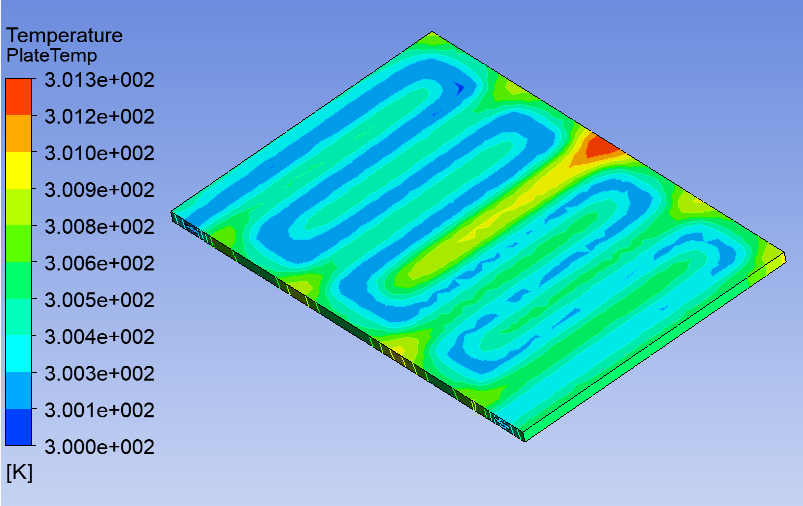
A serpentine channel cold plate was considered as the thermal management system for the Li-ion battery. The cross-section area of a channel was taken as 2 mm x 10 mm (the battery face area is 160 mm x 250 mm). The design with an optimal number of turns considering the maximum temperature of the battery, thermal gradient and pumping power required was chosen for further analysis. The optimised serpentine cold plate design is shown in Figure 1 and its temperature contour is shown in Figure 2.
The heat transfer coefficient and the pumping power for the cold plate at different inlet velocities were obtained using Ansys Fluent due to the complex analytical modelling of a serpentine channel. These values were considered for calculating the overall cost during the control optimisation.

2. 2. Thermal degradation models
To optimise the coolant flow, an appropriate cost/objective function needs to be determined that accurately captures the trade-off between thermal degradation and pumping power. The effect of pumping power / pumping energy consumed to circulate the coolant can be easily incorporated since the monetary cost associated with pumping energy increases linearly. Mathematically, the average power consumed E(τ) during the period of operation can be represented as follows:
Where Powp(t) is the instantaneous power consumed as a function of time and τ is the duration of operation. Incorporating the cost associated with thermal degradation is trickier and highly scenario-dependent. Various models can be used to incorporate the cost associated with thermal degradation. Some of them are as follows:
- Equilibrium temperature model - In this model, the equilibrium temperature Teq of the battery pack in steady-state operation is incorporated into the cost function along with the pumping energy consumed in such a way that as the equilibrium temperature increases, the cost increases.
- Linear thermal degradation model - In this model, the battery thermal life 𝐿(τ) reduces linearly when the temperature exceeds a critical value. Mathematically,
L0 represents the initial battery life in the absence of any thermal degradation
T(t) is the battery temperature at some time 0 ≤ 𝑡 ≤ τ
Tcrit is the critical temperature above which thermal degradation starts to occur
K(T) is the thermal degradation coefficient, which represents the reduction in the lifetime of the battery when the battery temperature exceeds the critical temperature by 1 unit for a unit time duration, where K(T) = 0 when T < Tcrit and K(T) = K0 when T > Tcrit
The total thermal damage Dmg(τ) to the battery is represented by;

The equilibrium temperature model is useful for optimising the steady state behaviour of the battery, which usually occurs under constant external power consumption. However, if the external power consumption is varying or fluctuating due to external factors like noise, then the thermal degradation model is more suitable since it takes into account the transient behaviour of the battery. However, the equilibrium temperature model has the advantage of being computationally less complex as compared to the thermal degradation model.
2. 3. Control optimisation
The decision variable(s) is the mass flow rate of the coolant as a function of time during the operation period of the battery, which is represented as f(t) in a continuous time setting. In a discrete-time setting, f(t) gets converted to an array/vector of flow rates, f[1:N] where 1,2,3, ..., N represent the time instances. Thus, there would be N decision variables in total. The size of the time step depends on the characteristic time/time constant of the battery.
For a given external power consumption Powext(t) and a decided flow rate f(t), the dynamics of the system are as follows:
Where D(t) is an intermediate variable that emerges from energy balance and I_drawn is the current drawn, which is also calculated based on energy balance. It is assumed that the power from the battery is used by the pump Powp(f(t)) and for external use Powext(t), without any loss of energy and Vol represents the voltage of the battery during operation.
The temperature as a function of time can be determined on the basis of lumped-mass analysis,

Idrawn2R represents the heat dissipated from the battery due to internal processes & h(f(t)) A (T(t)-Tcool) represents the heat absorbed by the coolant. R - effective resistance of the battery A - surface area for heat transfer to the coolant h(f(t)) – flow rate dependent heat transfer coefficient Tcool - Temperature of the coolant, which is maintained constant during operation (the temperature maintenance aspect is incorporated in Powp(f(t)) using a suitable correction factor)
For constant flow rate, the equilibrium temperature Teq can be obtained as:
Based on the equilibrium temperature model, the cost function 𝐶 can be defined as:

C1 is the cost per unit increase in the equilibrium temperature above critical temperature and C2 is the cost per unit increase in average pumping power consumed.
Based on the thermal degradation model, the cost function can be defined as:
Thus, Cdeg is the cost of operating the BTMS system per unit duration of service of the battery. After choosing the appropriate cost function based on the context, the optimisation problem can be formulated in continuous time as follows:
Minimize C subject to the following constraints;
1) D(t)>0,0≤t≤τ
2) 0≤f(t)≤fmax(t)
In discrete time, the optimisation problem can be formulated as follows - Minimize C subject to the following constraints;
1) D[n]>0,1≤n≤N
2) 0≤f[n]≤fmax
3. Results & Discussions
A software framework was created in MATLAB to obtain the optimal solution for flow rate as a function of time. The continuous time setting had to be converted to the discrete-time setting since all the operations needed to be performed numerically. The time step taken in this paper was 0.1s, ensuring a balance between the accuracy of the solution obtained and the computational time required. Since the optimisation problem is non-linear, the solver used for obtaining the optimal solution was fmincon, which utilises the interior point algorithm. A cascaded optimisation approach was utilised in which a close-to-optimum solution was obtained first, which was then used as the starting point for the next optimisation step. This made the process more efficient and led to faster convergence to the optimal solution as the first-order optimality value reached closer to zero quickly.
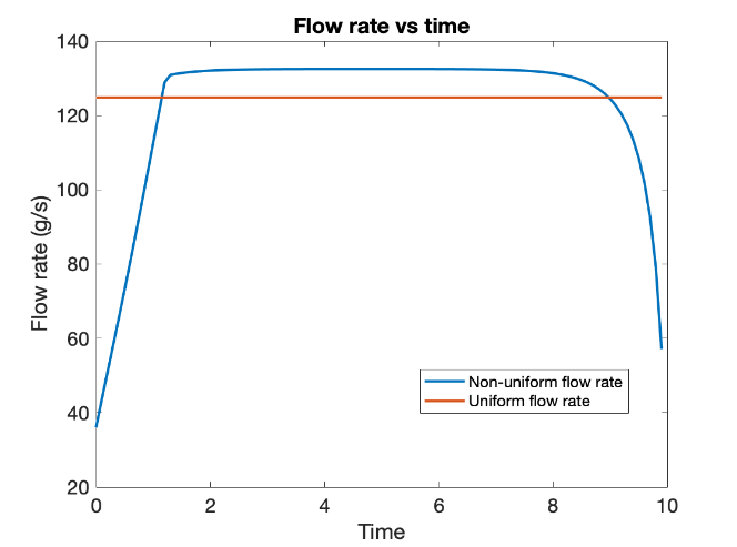
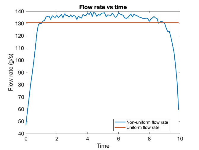
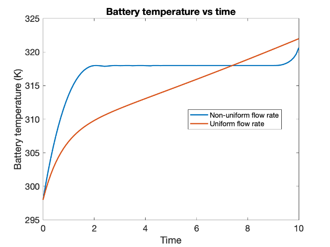
The results obtained below are based on the thermal degradation model for different external power consumption modes. The graph corresponding to uniform flow rate assumes that the flow rate cannot vary with time and the optimum value for constant flow rate is solved for. The graph for non-uniform flow rate relaxes the assumption used for uniform flow rate. This is done so as to compare the costs obtained in both cases. The cost in the case of a non-uniform flow rate should be lower than the uniform case since a uniform flow rate is technically a special case of a non-uniform flow rate.
(a)
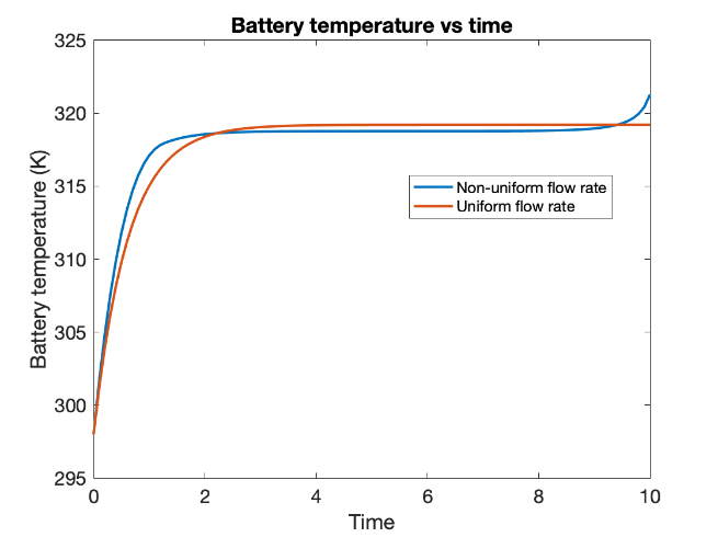
(b)
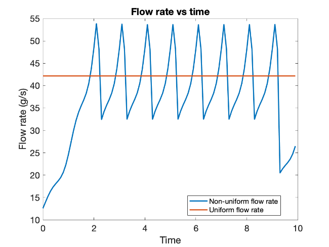
The graphs above show the optimal flow rate (in g/s) and battery pack temperature (K) as a function of time (in units of battery time constant) for a constant external power consumption corresponding to a heat dissipation of 10 W / cell. This was done to observe the effect of thermal damage on the optimal solution more evidently, as the peak temperature reached is greater than ideal.
In general, the optimal cooling strategy for high constant heat dissipation has three phases - i) increasing flow rate, ii) saturated flow rate and iii) decreasing flow rate. Thus, the flow rate as a function of time takes the shape of an upside-down U. It has been observed that not only is the overall objective value reduced for non-uniform flow rate, but even the total thermal damage and pumping energy consumed are reduced by 1-5% for the operating duration.
(a)
(b)
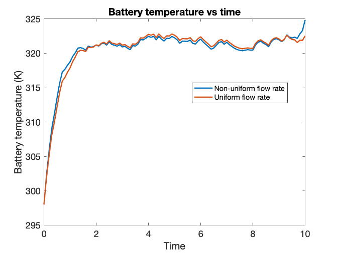
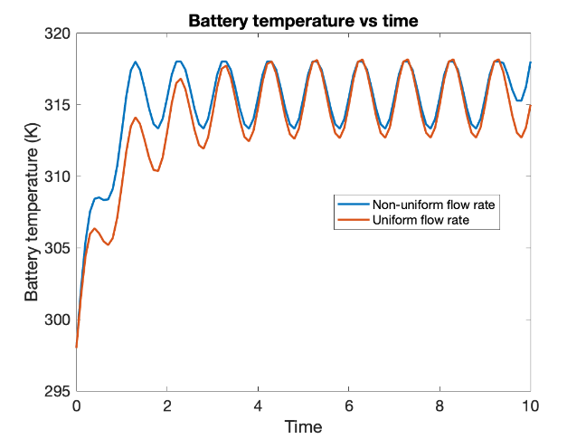
Our software framework also supports variable external power consumption, so the robustness of the cooling strategy to variation/fluctuations in external power drawn can be seen as well. The graphs above depict for the case of 10 W/cell subject to heat dissipation fluctuations. It is observed that the overall shape of the graph doesn’t alter that much.
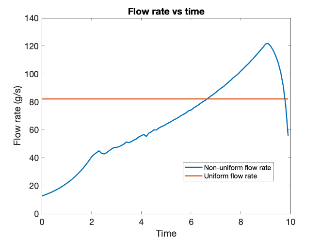
The graphs below depict the flow rate and battery temperature variation with time for linearly increasing power consumption (ramp power consumption) and sinusoidal power consumption respectively.
(a)
(b)
(a)
(b)
For the ramp power consumption scenario, since steady state is not really achieved when constant flow rate is used, it is important to vary the flow rate during the period of operation so that temperature doesn't shoot up significantly. It can be seen that for variable flow rate, the graph of temperature is close to what it would have been for steady-state operation.
The cost obtained for various cases is dependent on the values of the variables in the definition of the cost function, especially the variables of K(T) (thermal degradation coefficient), C1 (cost per unit increase in the temperature above critical temperature), C2 (cost per unit increase in average pumping power) and L_0 (initial battery life). The value of cost for different logical values of these parameters was considered. An improvement in the range of 1-5% of the cost was obtained for different set of variable values. The results obtained for a particular set of values (K(T) = 5, C1 = 1, C2 = 0.1 & L0 = 1000) are tabulated below. Although the percentage difference observed is ~1%, over a long duration and multiple charging cycles, the advantage of the optimal flow control becomes significant in absolute terms.
Table 1. Cost values for different cases for the above-mentioned parameter values.
|
Heat dissipation type |
Cost for constant flow rate |
Cost for optimal flow rate |
Percentage difference (%) |
|
Constant |
5.46E+03 |
5.40E+03 |
1.13 |
|
Fluctuating |
6.29E+03 |
6.24E+03 |
0.794 |
|
Ramped |
7.39E+03 |
7.33E+03 |
0.819 |
|
Sinusoidal |
4.81E+03 |
4.76E+03 |
1.05 |
4. Conclusion
Based on the results and the discussions, the following conclusions can be drawn. In general, the optimal cooling strategy for high constant heat dissipation has three phases during the operating duration - i) increasing flow rate, ii) saturated flow rate and iii) decreasing flow rate. The optimal cooling strategy is not greatly altered even in the presence of fluctuations, which implies that the cooling strategy is robust to external disturbances. The equilibrium temperature model is useful for optimising the steady state behaviour of the battery, while the thermal degradation model is more suitable if the external power consumption is varying due to factors like noise. Although we are able to obtain lower costs by varying the flow rate, the cost of the controller required to vary the flow rate properly has not been accounted for in this approach. Also, lumped analysis has been used for the dynamics of the system. Thus, it is unable to capture the effect of thermal gradients in the battery. The requirement for computational power increases greatly as we try to increase the operating duration of the battery. Thus, the current optimal control framework cannot be used for very long operating durations.
5. Acknowledgements
We would first like to express our sincere gratitude to IIT Bombay for giving us the opportunity and all required resources and guidance for carrying out this work. We would like to thank Prof. Avinash Bhardwaj, for his unwavering support and invaluable guidance throughout the course of this work. His expert advice, valuable insights, and dedicated mentorship significantly contributed to the successful completion of this paper.
References
[1] J. Kim, J. Oh, and H. Lee, "Review on battery thermal management system for electric vehicles," Applied Thermal Engineering, vol. 149. Elsevier Ltd, pp. 192-212, Feb. 25, 2019. doi: 10.1016/j.applthermaleng.2018.12.020. View Article
[2] P. R. Tete, M. M. Gupta, and S. S. Joshi, "Developments in battery thermal management systems for electric vehicles: A technical review," Journal of Energy Storage, vol. 35. Elsevier Ltd, Mar. 01, 2021. doi: 10.1016/j.est.2021.102255. View Article
[3] Ji, H., Luo, T., Dai, L., He, Z., & Wang, Q. (2023). Topology design of cold plates for pouch battery thermal management considering heat distribution characteristics. Applied Thermal Engineering, 224, 119940. https://doi.org/10.1016/j.applthermaleng.2022.119940 View Article
[4] Mo, X., Zhi, H., Ye, X., Hua, H., & He, L. (2021). Topology optimization of cooling plates for battery thermal management. International Journal of Heat and Mass Transfer, 178, 121612. https://doi.org/10.1016/j.ijheatmasstransfer.2021.121612 View Article
[5] Li, D., Zuo, W., Li, Q., Zhang, G., Zhou, K., & Jiaqiang, E. (2023). Effects of pulsating flow on the performance of multi-channel cold plate for thermal management of lithium-ion battery pack. Energy, 273, 127250. https://doi.org/10.1016/j.energy.2023.127250 View Article
[6] Shuai Ma, Modi Jiang, Peng Tao, Chengyi Song, Jianbo Wu, Jun Wang, Tao Deng and Wen Shang, "Temperature effect and thermal impact in lithium-ion batteries: A review," Progress in Natural Science: Materials International, vol. 28, no. 6. Elsevier B.V., pp. 653-666, Dec. 01, 2018. doi: 10.1016/j.pnsc.2018.11.002. View Article