Journal of Fluid Flow, Heat and Mass Transfer (JFFHMT)
ISSN: 2368-6111

Volume 11 - Year 2024 - Pages 09-20
DOI: 10.11159/jffhmt.2024.002
Efficient Cooling Approach with Integrated PCM Rooftops for Sustainable Load Reduction in Buildings with Natural Ventilation Systems
Amirhossein Khayyaminnejad1, Amir Fartaj1
1University of Windsor, Department of Mechanical, Automotive & Materials Engineering
401 Sunset Ave, Windsor, ON, Canada N9B 3P4
khayyam@uwindsor.ca; fartaj@uwindsor.ca
Abstract - Rising energy consumption presents a significant global challenge. Current data indicates that heating, ventilation, and air conditioning (HVAC) systems in residential sectors account for 40% of total energy usage, primarily sourced from non-renewable resources. In response to this challenge, scientists are actively exploring ways to decrease reliance on fossil fuels by harnessing renewable energy resources. This research article delves into the thermal performance of a natural ventilation system within a building located in Las Vegas, a city chosen for its hot and arid climate. The study focuses on the implementation of phase change material (PCM) during the peak of summer. The system under investigation comprises a solar chimney, an earth-to-air heat exchanger, and PCM. It is simulated using ANSYS Fluent software, with the RNG k-ε serving as the selected turbulence model. Based on the numerical simulations, n-Henicosane, is chosen specifically to assess its impact on the cooling load when applied to the roof. A key aspect of this research is the exploration of the effect of PCM layer thickness on the thermal performance of the natural cooling system. The natural ventilation system was found to reduce the peak indoor temperature by 15.5 K, resulting in a saving of 28.19 kW of energy during the day. Simulations revealed that the optimal thickness for the PCM layer is 70 mm. Upon integrating the PCM with this optimal thickness into the building, the maximum indoor temperature was further reduced by 2.5 K, reaching a comfortable 298.5 K. Remarkably, this system cut energy consumption by 81% at peak load, saving 33.21 kW over a 24-hour period. In conclusion, the integration of PCM into a building’s rooftop, coupled with a natural ventilation system, emerges as a wise strategy for reducing both indoor temperature and energy demand in hot and arid climates. This research underscores the potential of such sustainable solutions in addressing the pressing issue of increasing energy consumption.
Keywords: PCM, Solar chimney, Natural ventilation, CFD, Renewable energy.
© Copyright 2024 Authors - This is an Open Access article published under the Creative Commons Attribution License terms Creative Commons Attribution License terms. Unrestricted use, distribution, and reproduction in any medium are permitted, provided the original work is properly cited.
Date Received: 2023-06-18
Date Revised: 2024-01-01
Date Accepted: 2024-01-12
Date Published: 2024-01-16
1. Introduction
Worldwide energy consumption has increased as populations continue to grow and economies develop. Electricity plays a crucial role in meeting the energy demands of modern society. However, the majority of electricity production still relies on oil and natural gas, which contribute significantly to greenhouse gas emissions and climate change. By transitioning to renewable energy, it is possible to reduce dependence on non-renewable resources, mitigate the effects of climate change, and create a more sustainable future for generations to come. Renewable energy sources now account for over 29% of global electricity generation, according to the IEA [1]. The use of renewable energy resources is projected to grow in the coming years, with the IEA forecasting that renewable electricity generation driven by solar and wind power will increase by 50% between 2020 and 2025 [1].
Renewable energy can be used in several ways in Heating, Ventilation, and Air-Conditioning (HVAC) systems. Employing renewable energy in HVAC systems improves indoor air quality (IAQ) and indoor thermal conditions. By improving energy efficiency and reducing reliance on fossil fuels, HVAC systems powered by renewable energy can create healthier and more comfortable living and working environments while promoting sustainability and reducing the environmental impact of buildings.
Phase Change Materials (PCMs) have been successfully utilized in both residential and commercial sectors to regulate indoor temperatures and decrease the energy consumption of HVAC systems [2]. As a cost-effective and low-maintenance solution [3], PCMs significantly reduce energy consumption and enhance sustainability. PCMs function by mitigating the sun's heat gain, thereby helping maintain a lower temperature within the building. The PCM is typically encapsulated within a container or panel installed atop the roof. As the sun heats the roof, the PCM absorbs this heat, preventing it from permeating the building and thus maintaining a cooler indoor temperature [4]. Implementing PCMs on the roof leads to a decrease in the cooling load. This is because the radiation heat transfer between the roof and the sun is more significant than in other building parts. Therefore, the strategic placement of PCMs on the roof can significantly enhance the building's energy efficiency [5].
Many researchers have studied the effect of PCM on buildings in recent years. The inner surfaces of the walls and roof are chosen to study their temperature distribution [4,5] and heat transfer [6,7]. Li et al. [6] focused on the effect of using PCM on heat transfer through different roofs in a cold climate. They concluded that the PCM-integrated roofs strongly impacted the inner ceiling surface temperature. Moreover, the hottest indoor temperature was delayed beyond three hours compared with the non-PCM integrated roof. Pasupathy and Velraj [7] conducted a study to examine the thermal performance of a roof containing a phase change material (PCM) layer in a hot climate in India. Tokuç et al. [8] worked on PCM-integrated roofs experimentally and numerically. They claimed that the optimum PCM layer thickness is 20 mm for buildings in Mediterranean climates.
Jin and Zhang [9] studied the effect of Phase change materials in building insulation. Using PCM layers reduces fluctuations in indoor surface temperatures and heat fluxes. The PCM layer for cooling is more effective at reducing heat flux fluctuations than the heating layer. Alqallaf and Alawadhi [10] experimented to examine a roof design comprising a concrete slab with cylindrical holes containing PCM. They observed a reduction in heat flux at the indoor surface of the roof, up to 17%. Servando et al. [11] designed a new roof structure where PCM is encapsulated and fills the cavity of a hollow core slab. This innovative approach enhances the efficiency of cooling energy storage by utilizing ventilation during nighttime.
Beemkumar et al. [12] integrated a PCM layer into the roof experimentally. They studied the effectiveness of the PCM layer for a hot climate and figured out that integration of the PCM into the roof is able to postpone the heat transfer for ambient to the building and reduce the indoor temperature. Based on their experiments the indoor temperature maintained between 300 K and 301 K. Shi et al. [13] studied the effect of using ventilated PCM into the roofs during day and night experimentally. They reported that PCM integration can reduce the average indoor temperature by 3.68 °C, with an average reduction of 8.03%.
A solar chimney (SC), also known as a thermal chimney or solar updraft tower, is a passive solar ventilation system that utilizes the sun's energy to create airflow [14]. Solar chimneys can be used for passive cooling and ventilation in residential and commercial buildings. They offer a sustainable and energy-efficient alternative to conventional mechanical ventilation systems, as they rely solely on the sun's energy for operation [15]. Rabani et al. [16] experimentally studied solar chimney performance in Yazd, Iran. They achieved a 7 to 14 degrees reduction in indoor temperature during 24 hours. Amer et al. [17] studied Solar chimneys performance experimentally in Egypt, and their results revealed 8.5 degrees of indoor temperature reduction.
Earth-Air Heat Exchangers (EAHEs) are a promising technology for sustainable heating and cooling solutions, particularly in summer cooling. EAHEs utilize the earth's thermal inertia to moderate the air temperature used for ventilation, thereby reducing the load on conventional air conditioning systems [18]. The principle behind EAHEs is simple and effective. The system comprises a series of pipes, typically made of metallic, plastic, or concrete materials, buried at a certain depth in the ground [19]. The ambient air is drawn through these pipes, where it is cooled in the summer before being used for ventilation [19]. This cooling effect is achieved by leveraging the Earth's Undisturbed Temperature (EUT), which remains relatively constant throughout the year [4].
In summer, the EUT is lower than the ambient air temperature [20]. As the air moves through the pipes of the EAHE, it is moderated to the EUT, resulting in a cooling effect. This cooled air can then be used for ventilation, reducing the need for conventional air conditioning and thus lowering energy consumption. The performance of an EAHE system in summer cooling can be influenced by various factors, including the depth at which the pipes are buried, the diameter and length of the pipes, and the velocity of the airflow [20]. A longer pipe of a smaller diameter buried at a greater depth and having lower airflow velocity results in an increase in the performance of the EAHE system [4].
Integrating solar chimneys with geothermal air systems is a well-established strategy for reducing energy consumption and enhancing natural ventilation systems. This approach leverages EAHEs to tap into the energy stored within the ground. These systems' economic and environmental benefits have garnered considerable attention among designers and researchers [21]. In their theoretical research, Maerefat and Haghighi [22] explored the inclusion of a solar chimney with an EAHE, referred to as an SC-EAHE. They found that this SC-EAHE system could effectively cool and ventilate a room. Based on their findings, they proposed a coupled system designed to meet the thermal comfort needs of occupants.
Kalantar and Khayyaminejad [23] examined an SC-EAHE system in a separate study. They introduced a novel circular geometry for the solar chimney, constructed from glass and featuring a fin in the center. They simulated their system under the weather conditions of Yazd, Iran, on the hottest summer day. Their optimization of the natural ventilation performance revealed that their uniquely designed EAHE reduced the air temperature by 18 K. This finding underscores the potential of EAHEs in contributing to energy-efficient and comfortable indoor environments.
This paper examines the performance of the SC-EAHE [23] under the weather conditions of Las Vegas for the first time. Additionally, it explores the impact of integrating Phase Change Materials (PCMs) into the roof on the proposed natural ventilation and cooling performance. Three models of PCMs are incorporated into the roof structure, and the influence of the PCM layer's thickness is investigated by considering four different thicknesses.
2. Problem statement
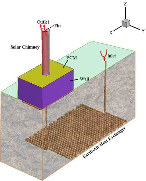
A single-story building is modeled, and the thermal performance of the natural ventilation system is investigated during summer in Las Vegas, with a cylindrical solar chimney on the rooftop and an EAHE buried in the soil under the building. This combination of the equipments is called natural ventilation system. The passive cooling and natural ventilation system is employed to provide thermal comfort conditions for residents in a building (6 m (length) × 4 m (width) × 3 m (height)). A three-directional vertical fin, which is made of copper, has a common centreline with the chimney. This geometry of SC results in absorbing solar radiation in all directions (360°) and longer time during the day compared with Inclined solar chimneys. In addition, by using this three-dimensional fin, the absorption area is increased compared with traditional solar chimneys, leading to higher efficacy of solar chimneys.
EAHE is buried beneath the building. Hot airflow passes through the EAHE pipes, losing heat to the cool pipes buried in the soil. The length of the pipes allows the air to reach the minimum temperature. The air flows upward, divided into four sections with registers in the building's corners, improving air circulation. The temperature difference between the registers and the solar chimney outlet results in buoyancy-driven flow (natural convection ventilation), with negative pressure at the EAHE inlet and positive pressure at the chimney outlet.
Figure 1 illustrates the simulated components. As it can be seen, hot outdoor air is cooled in EAHE, and then the cool air enters the building, and after cooling the air, air flows into the solar chimney, then its temperature increases and then flows out of the building. Their results [23] show that the SC height and diameter are 6 and 1 meters, respectively. The SC is equipped with three fins. Additionally, EAHE is buried at a depth of 7 meters, and EAHE's pipes have a diameter of 0.2 meters and a total length of 270 meters.
Previous investigations have revealed that Las Vegas experiences desirable soil temperatures at a depth of 4 meters [24]. Since PCM is utilized to improve the natural system efficiency, it is expected that by implementing PCM on the roof, the peak cooling load will decrease [4], and room temperature will be more stable [5] due to the latent heat gain. In addition, using PCM helps reduce the heat transfer through the building envelope, which delays indoor temperature rise.
3. Numerical modelling
ANSYS Fluent 2022 R1 is employed to simulate the model using Computational Fluid Dynamic (CFD) equations and Finite Volume Method (FVM). A transient pressure-based type of solver is preferred with a SIMPLE algorithm approach to solve Pressure-Velocity equations. The selected time step is 60 seconds. Boussinesq Model calculates air density. Furthermore, the Solidification and melting features are activated [25].
Fluid flow is assumed to be three-dimensional, unsteady, and incompressible. Reynolds Averaged Navier–Stokes (RANS) numerical method is used to solve the fluid flow equations [25]. Governing equations are Continuity, mass conservation (Eq. 1) and, the conservation of momentum (Eq. 2), energy conservation (Eq. 3) equations are given below.
Where ρ represents fluid density, V , T and P indicate fluid velocity, Temperature and pressure, respectively. Also H, μ, g and t defined as enthalpy, Fluid viscosity, gravitational accelerate and time, respectively.
In order to model the buoyancy driven flow of the air due to the natural convection, the Boussinesq approximation (Eq. 4) is used. In the Boussinesq approximation, variations in fluid properties other than density are ignored, and density only appears when it is multiplied by g, the gravitational acceleration. The approximation assumes a linear change in density that is dependent on temperature [26]. It is very accurate for natural convection flows at relatively low-temperature differences from ambient. The Boussinesq approximation is applied to problems where the fluid varies in temperature from one place to another, driving a flow of fluid and heat transfer [27]. The fluid satisfies conservation of mass, conservation of momentum, and conservation of energy. However, it’s important to note that the Boussinesq approximation should not be used if the temperature differences in the domain are large. In addition, it cannot be used with species calculations, combustion, forced convection or reacting flows. In the Eq. 4, β is the fluid thermal expansion coefficient.
Moreover, to calculate the overall heat transfer through the PCM is given in Eq. 5, and sensible heat Qsensible (Eq. 6) for PCMs calculate based on enthalpy.


Where CP indicates fluid specific heat. The latent heat portion is calculated based on Eq. 7. Besides, in Eq. 8, θ represents the liquid fraction, while Γ denotes the latent heat of PCM. The fraction of liquid can be changed from “0” to “1” to obtain from [28]:

The RNG k-ε turbulence model (Eqs. 9 – 10) is based on the normalization group method applied to the conservation equation. Its advantage compared to other models is containing Rε, to predict fluid flow behavior more accurately [29].


The Rε is given as Eq. (11) Where η≡Sk/ε, η0=4.38, β=0.012. Gk and Gb indicate the production of turbulence kinetic energy based on mean velocity gradients, and buoyancy, respectively [30]. Prandtl numbers for k and ε are defined as αk and αε. Source terms for k and ε are set by the user based on the boundary conditions. YM represents the fluctuations in turbulence over dissipation rate.
4. Boundary Conditions
This simulation is done based on Las Vegas Weather data on July 1st, which is the hottest day in the year. Based on the literature [24] the assumed ambient temperature in simulation differs during hours of the day. The desired indoor temperature falls within the range of 293.15 K to 299.15 K.
To simulate solar load, a ray-tracing solar load model is employed. This model is particularly useful in applications such as automotive climate control and human comfort modeling in buildings. The Solar Ray Tracing algorithm predicts the direct illumination energy source that results from incident solar radiation. It takes a beam modeled using the sun position vector and illumination parameters, applies it to any specified wall or inlet/outlet boundary zones, performs a face-by-face shading analysis to determine well-defined shadows on all boundary faces and interior walls, and computes the heat flux on the boundary faces that results from the incident radiation. It’s important to note that the Solar Ray Tracing only tracks a ray until it reaches the first opaque wall. After this, no further ray tracing is done, and with this, no “real” reflection. The latitude and longitude coordinates of Las Vegas, Nevada, United States, are 36.1699° N and -115.1398° W. Las Vegas elevation is 610 m above sea level and the operating pressure. Ambient and soil temperature are imported to ANSYS FLUENT by User Defined Functions (UDF)[22,31].
PCM is selected based on the working condition. The best PCM in this application is the one with having similar melting point to the peak load temperature [3,21]. The selected PCMs are n-Henicosane (C21) with melting point of 314.15 K, solidification point of 312.15 K, latent heat of 210 kJ/kg, and thermal conductivity of 0.2 W/mK [23]. n-Eicosane (C20) with melting point of 311.15 K, solidification point of 309.15 K, latent heat of 246 kJ/kg [32]. RT35HC with melting point of 309.15 K, solidification point of 307.15 K, latent heat of 215 kJ/kg [33]. Thermal expansion coefficient for air is assumed 0.0034 1/K. EAHE pipes are made of clay, and their thickness is 0.015 m. R-22 is selected as Building wall insulation [34]. The solar chimney includes 10 mm clean glass and assumed as semi-transparent while other components assumed as opaque. Fin's thermal boundary conditions are selected as coupled. In this simulation, all components participate in the solar load calculation model except EAHE.
5. Grid Study
The grid independency approach aims to determine the optimal cell number for accurate simulation while keeping computational costs in check. In this phase, the geometry is examined with six different cell numbers (from 752,736 to 5,683,423) to identify a suitable cell count. Based on the simulations data which is shown in Table 1, results converged for geometries more than 2,767,896 cell number. There was a 0.075% difference in average indoor temperature between 2,767,896 cells and 4,183,355 cells. Therefore, the mesh network with 2,767,896 cells is taken into consideration for further simulation.
Table 1. Results comparison of seven different trials.
|
Number of cells |
EAHE Outlet Temperature (K) |
Room Temperature (K) |
|
752,736 |
12.30 |
300.15 |
|
1,036,851 |
12.22 |
300.20 |
|
1,534,890 |
12.15 |
300.30 |
|
1,953,820 |
12.10 |
300.38 |
|
2,767,896 |
12.03 |
300.48 |
|
4,125,239 |
12.01 |
300.50 |
|
5,683,423 |
12.01 |
300.50 |
Figure 2 shows the final generated mesh for the studied geometry. The ANSYS Meshing module is utilized to produce an unstructured non-uniform polyhedral network. Meshing is done by setting characteristics like growth rate (1.10), the cell size range (0.05 -150 mm), and total number of cells was 2,767,896. Figure 2 (b), also shows the prism layer of the generated mesh for the EAHE pipes. As it can be seen, 5 layer with 10% growth rate are considered as boundary layer mesh to increase the accuracy of the numerical simulation by capturing the fluid behaviour near the wall.
Using of polyhedral meshes has been found to offer several distinct advantages over other mesh types, such as tetrahedral meshes. One of the key benefits lies in the structure of the polyhedral mesh itself. Each individual cell within the mesh is surrounded by numerous neighboring cells. This unique configuration facilitates a more accurate approximation of gradients, thereby enhancing the precision of the computations involved [35]. Moreover, polyhedral cells are characterized by a lower degree of distortion compared to their tetrahedral counterparts. This attribute contributes to a higher overall quality of the cells, which in turn, leads to improved accuracy in the simulation results. Another noteworthy advantage of polyhedral cells is their ability to better represent different flow alignments [36]. This capability allows for a more realistic modeling of fluid flow, thereby providing more reliable and accurate results. In terms of computational efficiency, polyhedral meshes often exhibit faster and more robust convergence to lower residual values. This means that solutions can be obtained more quickly, reducing the computational time and resources required [37]. Furthermore, polyhedral meshes have been found to deliver equivalent accuracy results compared to other mesh types, but with fewer iterations and faster solution runtimes [36]. This efficiency makes polyhedral meshes a preferred choice for complex simulations where computational resources may be a limiting factor [36]. Lastly, polyhedral meshes display less sensitivity to stretching than tetrahedral meshes [35]. This characteristic results in better numerical stability of the model, thereby reducing the likelihood of computational errors and enhancing the reliability of the simulation results.
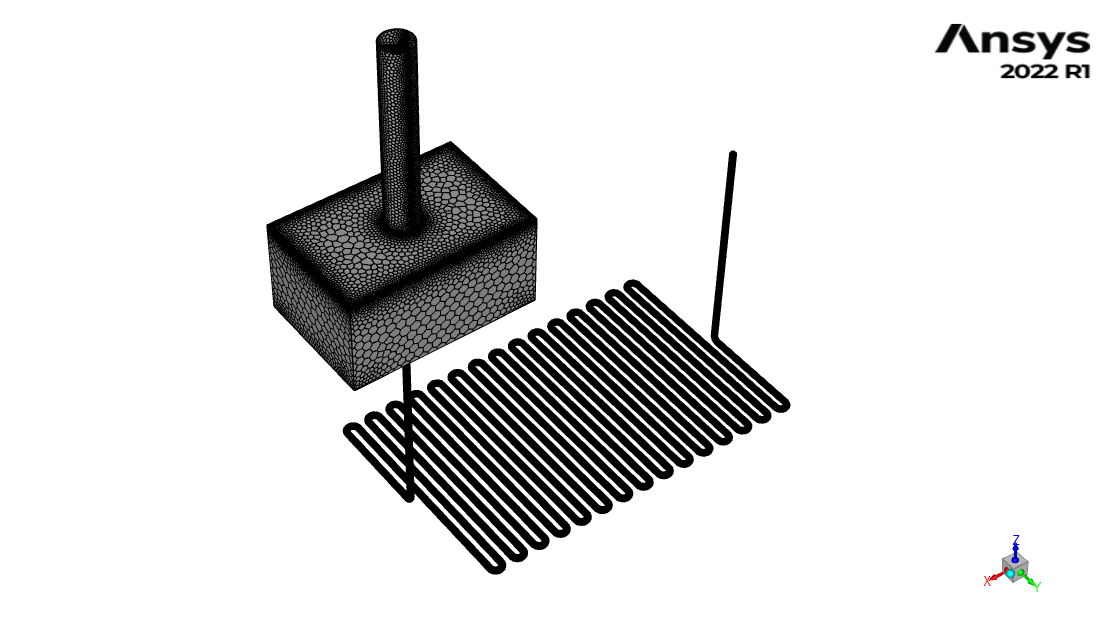
(a)

(b)
6. Validation
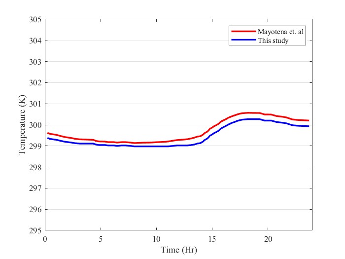
Maytorena et. al [4] analyzed thermal performance of an EAHE for cooling a room in Mexican desert climate. They simulated their model by Ansys Fluent and verified their simulation with an experimental model. in addition, Maytorena et. al [4] used PCM on the roof to enhance their system performance. In the current paper, numerical study of Maytorena et. al [4] is simulated to verify the accuracy of the numerical simulation and mathematical model. Figure 3 shows temperature of ceiling of the room with PCM in current study and Maytorena et. al [4]. Results are in a good agreement and the maximum error is 1.4% which is occurred at the time of 14:15.
7. Results and Discussion
In this part, two sections of the simulation will be discussed. The first one is a simulation of the natural ventilation system in Las Vegas, and the second one, the effect of PCM’s thickness, is studied.
7. 1. System Performance in Las Vegas, USA
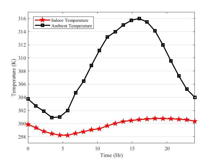
The passive ventilation and cooling system is simulated in Las Vegas, USA. The average indoor and ambient temperatures are given in Figure 4. The disparity between ambient and indoor temperatures can indicate the effectiveness of the SC-EAHE system. This parameter is variable between 1.8 and 15.5 K. The passive cooling system is more effective in hot hours of the day when the temperature difference between ambient and indoor is between 6 and 15.5 K. In other words, the passive cooling system plays an important role when the outdoor temperature and cooling load are higher. The SC-EAHE system maintains the indoor temperature between 298.5 and 330.5 K. Another parameter that can be analyzed is the temperature fluctuation over 24 hours. The indoor temperature range throughout the day is 2.5 K.
7. 2. Effect of different PCM models
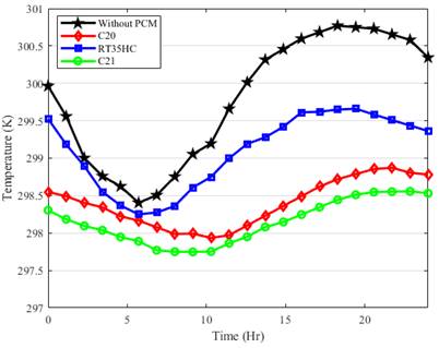
PCMs are implemented on the roof. Figure 5 illustrates the indoor temperature over a 24-hour period when different PCMs are added. According to the temperature graph in Figure 5, the maximum room temperature using RT35HC, C20, and C21 (n-Henicosane) PCMs is 299.6 K, 298.8 K, and 298.5 K, respectively. However, the minimum temperature shows a different trend among the PCMs. The indoor minimum temperature in the room using RT35HC, C20, and C21 is 298.4 K, 298.0 K, and 297.7 K, respectively. This indicates that the indoor temperature experienced a more stable temperature throughout the day, fluctuating only 0.9 K by implementing C21 PCM. Moreover, the indoor temperature will be cooler when using the C21 PCM.
The difference in the indoor temperature among these scenarios could be based on differences between PCM melting point and Latent heat gain. The C21 has the optimum response because its melting point is a bit higher than the peak temperature so that it can reduce the peak load more effectively. In addition, Since its latent heat is higher, implementing this PCM would increase the overall heat gain. This pattern and behavior of different PCMs are in good agreement with the previous studies [28, 29]. As it can be seen, the indoor temperature during the peak temperature time is reduced by 1.1 K and 2.3 K by implementing RT35HC and C21, respectively. This shows that the RT35HC is less effective than C21 in postponing the heat transfer during the peak temperature. This is caused by the lower melting point of the RT35HC, which makes it inappropriate for this ambient condition.
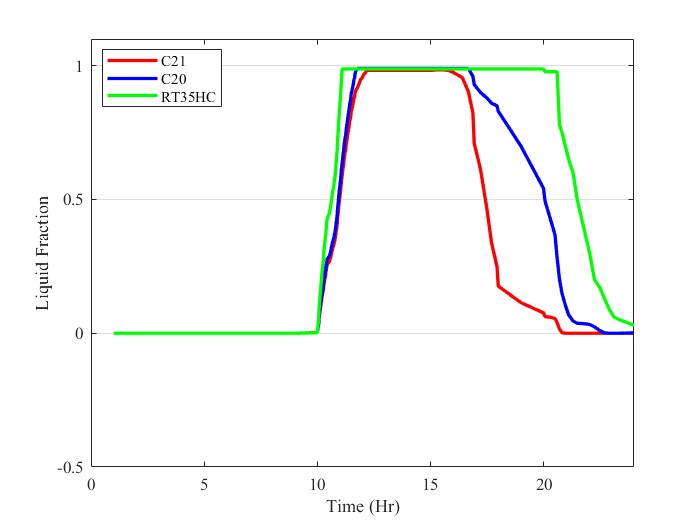
In Figure 5, the difference in indoor temperature among the studied cases increases when the PCM starts melting. From 5:00 until 11:25, the difference between the case without PCM and other cases is different. This shows the effectiveness of the integrated PCM. As shown, the indoor temperature started decreasing during the mentioned time for the C20 and C21. At the same time, RT35CH experiences an increasing trend. This difference in the PCM effectiveness occurred due to the lower melting point of the RT35HC. This means that based on the ambient temperature, the PCM should have a higher melting point near the peak ambient temperature to reduce the indoor temperature, which increases the PCM's effectiveness. The impact of the melting/ solidification point is more evident when studying the liquid fraction graph.
On the other hand, they exhibit noticeable differences in their behavior. For instance, RT35HC, which has the lowest melting point, started the melting process earlier, while C21, which has a higher melting point, started this process later than the others. It’s worth noting that as the day begins, the temperature rises, and the solar load increases. Consequently, two modes of heat transfer - radiation from the sun and convection from the ambient - play a role in increasing the PCM temperature and its melting, respectively.
The duration that the PCM remains melted is shortest for C21, while this time is longer for C20 and RT35HC. This is due to the higher melting point of C21, which results in earlier solidification. Another behavior that can be discussed is the solidification duration, which indicates how long the solidification process lasts. As observed, C20 has the most extended solidification duration, taking 5 hours and 14 minutes. This parameter for RT35HC and C21 is 5 hours 4 hours, and 22 minutes, respectively. This occurs because of the higher latent heat of C20 compared to the others.
Furthermore, it is noteworthy that the rate of change in the liquid fraction magnitude over time varies among these PCMs. Upon examination, it is evident that C21 exhibits the steepest slope, while C20 has the least steep slope. This observed trend is intrinsically linked to the latent heat capacity of the PCM. Specifically, C20, which possesses a higher latent heat capacity, demonstrates a lower slope. This phenomenon can be attributed to the PCM’s attempt to dissipate heat. Consequently, a higher latent heat capacity results in a slower reduction speed of the liquid fraction, as the PCM expends more time in the phase transition due to the more significant amount of heat to be released.
The optimal PCM is the one that has a melting point at the same temperature as the peak load. Based on the hourly ambient temperature of Las Vegas, the peak load and temperature occur at 314.15 K. This suggests that the findings in these simulations agree with PCM behavior and results reported in the literature. In addition, based on the discussions, selecting a PCM with a melting temperature near the peak load temperature is preferable rather than a PCM with a higher latent heat is preferable.
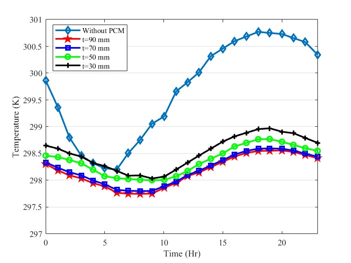
7. 2. Effect of PCM thickness
Four different thicknesses (30 mm, 50 mm, 70 mm, and 90 mm) are selected to investigate the effect of PCM layer thickness. Figure 7 shows the hourly indoor temperature for different thicknesses. The effectiveness of the PCM layer on the system’s thermal performance is more sensible in hot hours of the day. The average indoor temperature is warmer when the PCM layer is 30 mm thick. The indoor temperature experienced cooler conditions by increasing PCM thickness to 90 mm.
The difference in Indoor maximum temperature between 70 mm and 90 mm is 0.05%, which means that by adding 20 mm of PCM when the PCM thickness is already 70 mm, the indoor temperature will remain constant. By increasing thickness from 30 mm to 70 mm, the peak indoor temperature is reduced by 0.6 K. By adding a PCM layer with 70 mm thickness. Also, the temperature range is 2.5 K without PCM, while this parameter reaches 0.8 K after using PCM.
7. 3. Energy Saving
Figure 8 shows the hourly temperature of Ambient temperature, the indoor temperature in the presence of SC-EAHE, and the indoor temperature using SC-EAHE with PCM. For the hottest hour of the day, SC-EAHE reduces Indoor temperature to 300.5 K, and by using SC-EAHE, the indoor temperature reaches 298.5 K. Furthermore, using PCM is more effective during the time that the building is experiencing the peak load. Peak load is the highest amount of demanded cooling to maintain the indoor air in the comfort zone.
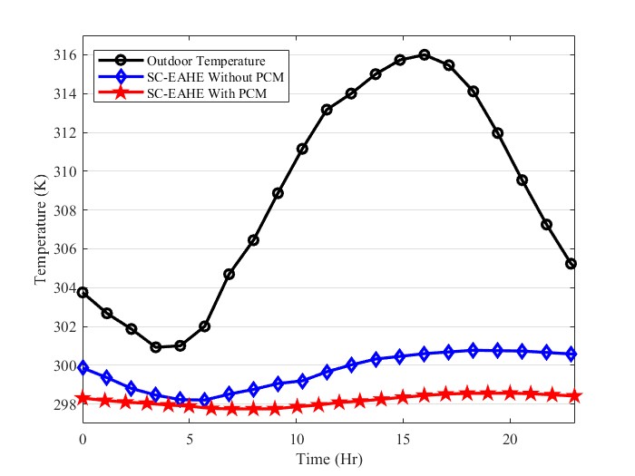
Figure 9 illustrates the Hourly cooling load of the building and the amount of supported cooling load by the passive cooling system. The peak load is 3.15 kW at 15:30. At the same time, SC-EAHE saves up to 2.25 kW and supports 71% of the cooling load. By integrating PCM, the passive cooling system saves up to 2.56 kW and provides 81% of the cooling load. SC-EAHE system saves 28.19 kW during 24 hours, while by adding PCM, saved energy increases to 33.21 kW.
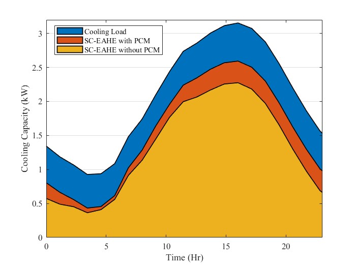
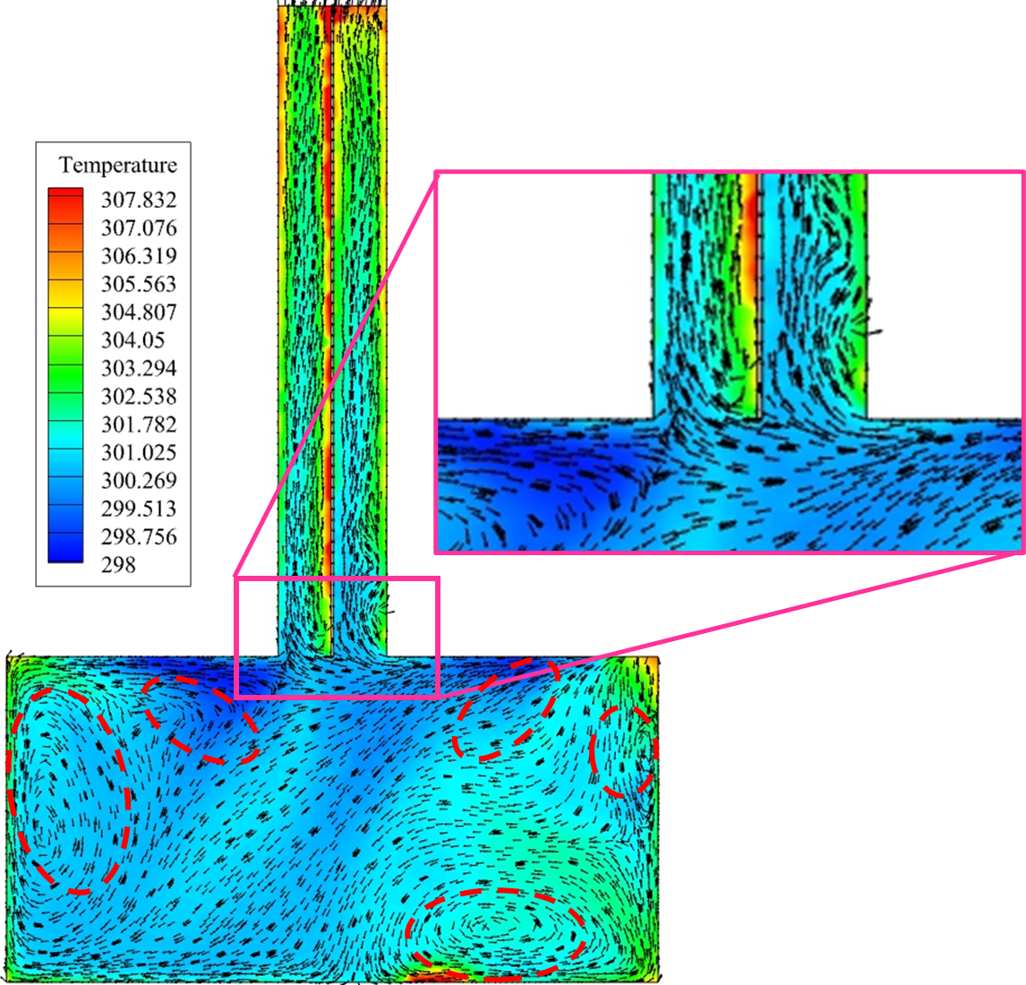
Figure 10 illustrates the indoor air temperature at 17:22, where the indoor air experiences the maximum indoor temperature. As can be seen, the average air temperature in the building is lower than the average air temperature in the SC. The average indoor temperature is 301.23 K, and the average SC outlet temperature is 330.8 K. The average temperature of the EAHE, which is the registered air to the building, is 298.3 K. The figure also illustrates the fluid flow path and the formation of vortices. The most substantial vortices are observed where the registered air makes contact with the ceiling and subsequently descends, resulting in a circulation pattern within the building. This pattern detects separation points near the SC inlet from the roof. Furthermore, integrating a PCM layer on the roof decreases the temperature experienced by the inner surface of the ceiling. This observation aligns with data reported by previous scholars [4,7,9], thereby validating the effectiveness of PCM integration in enhancing thermal performance.
8. Conclusion
This study investigates the thermal performance of a natural ventilation and cooling system during the peak of summer in Las Vegas. The findings reveal that the system can effectively reduce the indoor temperature of a building by up to 15.5 K and decrease the cooling load by 71% at the highest ambient temperature. Notably, the system saved 28.19 kW of energy consumption throughout the day.
The study also explored the integration of Phase Change Material (PCM) on the rooftop, in conjunction with the Soil-Coupled Earth-Air Heat Exchanger (SC-EAHE) system. This combination further reduced the indoor temperature by 2.5 K at the peak ambient temperature and decreased the cooling load by 33.21 kW for the entire day.
Simulation results identified the C21 (n-Henicosane) as the most effective PCM model, as it maintained a more stable and lower indoor temperature. Consequently, the use of this passive ventilation and cooling system reduces the workload of the air conditioning system, leading to decreased maintenance and utility costs.
The system’s significant reduction in indoor temperature, cooling load, and energy consumption not only enhances occupant thermal comfort but also contributes to environmental sustainability by reducing dependence on traditional air conditioning systems. These findings hold practical implications for architects, engineers, and policymakers in designing and implementing energy-efficient and sustainable cooling strategies for buildings in climates similar to Las Vegas.
References
[1] "Renewables 2021 dataset - Data product - IEA," IEA. View Article
[2] M. Momeni, S. Askar, and A. Fartaj, 'Thermal performance evaluation of a compact two-fluid finned heat exchanger integrated with cold latent heat energy storage', Appl. Therm. Eng., vol. 230, no. 120815, p. 120815, Jul. 2023. View Article
[3] Jalilian, Saman, Mahdi Momeni, and Amir Fartaj. "Enhancing thermal performance and optimization strategies of PCM-integrated slab-finned two-fluid heat exchangers for sustainable thermal management." Journal of Energy Storage 75 (2024): 109587. View Article
[4] V. M. Maytorena, J. F. Hinojosa, S. Moreno, and D. A. Buentello-Montoya, Thermal performance analysis of a passive hybrid earth-to-air heat exchanger for cooling rooms at Mexican desert climate. Case Studies in Thermal Engineering. 2023. View Article
[5] K. W. Shah, P. J. Ong, M. H. Chua, S. H. G. Toh, J. J. C. Lee, X. Y. D. Soo, Z. M. Png, R. Ji, J. Xu, and Q. Zhou, 'Application of phase change materials in building components and the use of nanotechnology for its improvement', Energy Build., vol. 262, no. 112018, p. 112018, May 2022. View Article
[6] D. Li, Y. Zheng, C. Liu, and G. Wu, 'Numerical analysis on thermal performance of roof contained PCM of a single residential building', Energy Convers. Manag., vol. 100, pp. 147-156, Aug. 2015. View Article
[7] A. Pasupathy and R. Velraj, 'Effect of double layer phase change material in building roof for year round thermal management', Energy Build., vol. 40, no. 3, pp. 193-203, 2008. View Article
[8] A. Tokuç, T. Başaran, and S. C. Yesügey, 'An experimental and numerical investigation on the use of phase change materials in building elements: The case of a flat roof in Istanbul', Energy Build., vol. 102, pp. 91-104, Sep. 2015. View Article
[9] X. Jin and X. Zhang, "Thermal analysis of a double layer phase change material floor," Applied Thermal Engineering, vol. 31, no. 10, pp. 1576-1581, Jul. 2011, doi: 10.1016/j.applthermaleng.2011.01.023. View Article
[10] H. J. Alqallaf and E. M. Alawadhi, 'Concrete roof with cylindrical holes containing PCM to reduce the heat gain', Energy Build., vol. 61, pp. 73-80, Jun. 2013. View Article
[11] S. Álvarez, L. F. Cabeza, A. Ruiz-Pardo, A. Castell, and J. A. Tenorio, 'Building integration of PCM for natural cooling of buildings', Appl. Energy, vol. 109, pp. 514-522, Sep. 2013. View Article
[12] Beemkumar, Nagappan, et al. "Control of room temperature fluctuations in the building by incorporating PCM in the roof." Journal of Thermal Analysis and Calorimetry 143 (2021): 3039-3046. View Article
[13] Shi, Yu, et al. "Experimental study of the thermal insulation performance of phase-change ventilated roofs." Energy and Buildings 303 (2024): 113819. View Article
[14] M. S. B. Jahromi, V. Kalantar, H. S. Akhijahani, H. Kargarsharifabad, and S. Shoeibi, 'Performance analysis of a new solar air ventilator with phase change material: Numerical simulation, techno-economic and environmental analysis', Journal of Energy Storage, vol. 62, 2023. View Article
[15] S. Jafari and V. Kalantar, 'Numerical simulation of natural ventilation with passive cooling by diagonal solar chimneys and windcatcher and water spray system in a hot and dry climate', Energy Build., vol. 256, no. 111714, p. 111714, Feb. 2022. View Article
[16] R. Rabani, A. K. Faghih, M. Rabani, and M. Rabani, 'Numerical simulation of an innovated building cooling system with combination of solar chimney and water spraying system', Heat Mass Transf., vol. 50, no. 11, pp. 1609-1625, Nov. 2014. View Article
[17] E. H. Amer, "Passive options for solar cooling of buildings in arid areas," Energy, vol. 31, no. 8-9, pp. 1332-1344, Jul. 2006, doi: 10.1016/j.energy.2005.06.002. View Article
[18] Bisoniya, Trilok Singh. "Design of earth-air heat exchanger system." Geothermal Energy 3 (2015): 1-10. View Article
[19] Anshu, Kumari, Prashant Kumar, and Basudev Pradhan. "Numerical simulation of stand-alone photovoltaic integrated with earth to air heat exchanger for space heating/cooling of a residential building." Renewable Energy 203 (2023): 763-778. View Article
[20] Goyal, V., Asati, A. K., & Arora, A. (2023). An Experimental and Modeling Study for a Novel Bank-Type Earth Air Heat Exchanger for the Summer Season Using Full Factorial Design. Journal of Thermal Science and Engineering Applications, 15(2), 021006. View Article
[21] R. Elghamry and H. Hassan, "An experimental work on the impact of new combinations of solar chimney, photovoltaic and geothermal air tube on building cooling and ventilation," Solar Energy, vol. 205, pp. 142-153, Jul. 2020, doi: 10.1016/j.solener.2020.05.049. View Article
[22] M. Maerefat and A. P. Haghighi, 'Passive cooling of buildings by using integrated earth to air heat exchanger and solar chimney', Renew. Energy, vol. 35, no. 10, pp. 2316-2324, Oct. 2010. View Article
[23] V. Kalantar and A. Khayyaminejad, 'Numerical simulation of a combination of a new solar ventilator and geothermal heat exchanger for natural ventilation and space cooling', Int. J. Energy Environ. Eng., vol. 13, no. 2, pp. 785-804, Jun. 2022. View Article
[24] R. Vidhi, "A Review of Underground Soil and Night Sky as Passive Heat Sink: Design Configurations and Models," Energies, vol. 11, no. 11, p. 2941, Oct. 2018, doi: 10.3390/en11112941. View Article
[25] Khayyaminejad, Amirhossein, and Amir Fartaj. "Passive Cooling Strategy for Reducing Load in a Building with an Integrated PCM on the Rooftop.". Proceedings of the 4 th International Conference on Fluid Flow and Thermal Science (ICFFTS'23). Lisbon, Portugal. doi: 10.11159/icffts23.144 View Article
[26] Mayeli, Peyman, and Gregory J. Sheard. "Buoyancy-driven flows beyond the Boussinesq approximation: A brief review." International Communications in Heat and Mass Transfer 125 (2021): 105316. View Article
[27] Zhou, Yu, et al. "Predictive accuracy of Boussinesq approximation in opposed mixed convection with a high-temperature heat source inside a building." Building and Environment 144 (2018): 349-356. View Article
[28] M. Momeni and A. Fartaj, 'Numerical thermal performance analysis of a PCM-to-air and liquid heat exchanger implementing latent heat thermal energy storage', J. Energy Storage, vol. 58, no. 106363, p. 106363, Feb. 2023. View Article
[29] T. Tsumura, T. Kunihiro, and K. Ohnishi, "Derivation of covariant dissipative fluid dynamics in the renormalization-group method," Physics Letters B, vol. 646, no. 2-3, pp. 134-140, Mar. 2007, doi: 10.1016/j.physletb.2006.12.074. View Article
[30] A. Khayyaminejad, N. P. Khabazi, F. Gholami-Malek Abad, and S. Taheripour, (2023). Numerical Investigation on the Effect of the Geometric Parameters of the Impeller on Vortex Pump Performance. Iranian Journal of Science and Technology, Transactions of Mechanical Engineering, 1-21. View Article
[31] Liu, L., Hammami, N., Trovalet, L., Bigot, D., Habas, J. P., & Malet-Damour, B. (2022). Description of phase change materials (PCMs) used in buildings under various climates: A review. Journal of Energy Storage, 56, 105760. View Article
[32] Zhang, F., Jiang, F., Xu, Z., Yu, W., Bai, Y., & Liu, W. (2023). Effect of thermal parameters on heat storage and release performance of phase change material composite wall. Energy Exploration & Exploitation, 41(2), 619-635. View Article
[33] Momeni, Mahdi, Saman Jalilian, and Amir Fartaj. "Thermal Response Analysis of a Cross-Flow PCM Heat Exchanger Based on Air and Liquid Flow." Journal of Fluid Flow, Heat and Mass Transfer (JFFHMT) 10.1 (2023): 86. View Article
[34] Goel, Surpriya, et al. Enhancements to ASHRAE standard 90.1 prototype building models. No. PNNL-23269. Pacific Northwest National Lab.(PNNL), Richland, WA (United States), 2014.
[35] Brezzi, Franco, et al. "A new discretization methodology for diffusion problems on generalized polyhedral meshes." Computer Methods in Applied Mechanics and Engineering 196.37-40 (2007): 3682-3692. View Article
[36] Sosnowski, Marcin, et al. "Polyhedral meshing in numerical analysis of conjugate heat transfer." EPJ Web of Conferences. Vol. 180. EDP Sciences, 2018. View Article
[37] Chen, Haofu, et al. "Application of polyhedral meshing strategy in indoor environment simulation: Model accuracy and computing time." Indoor and Built Environment 31.3 (2022): 719-731. View Article