Journal of Fluid Flow, Heat and Mass Transfer (JFFHMT)
ISSN: 2368-6111

Volume 11 - Year 2024 - Pages 01-08
DOI: 10.11159/jffhmt.2024.001
Design and Numerical Characterization of SAR (Y-U)H Micromixers
Md Readul Mahmud
Independent University, Bangladesh (IUB), Department of Physical Sciences
Plot 16 Block B, Aftabuddin Ahmed Road Bashundhara R/A, Dhaka-1229, Bangladesh
mahmud.readul@iub.edu.bd
Abstract - A new micromixer named ‘(Y-U)H’ is proposed based on the split and recombine (SAR) principle. Five different (Y-U)H mixers are constructed with varying vertical cylindrical connector height H. The optimization is carried out by changing the height H from 0 mm to 0.8 mm at varying Reynolds numbers ranging from 1 to 100 using numerical simulation software Ansys 15. The numerical setup is validated by comparing the numerical data with the experimental results of a well-known SAR ‘H’ mixer. Proposed (Y-U)H mixers have superior mixing performance than the H mixer irrespective of Reynolds numbers. Furthermore, the (Y-U)H mixers show excellent efficiency (η>90%) at low Reynolds numbers (Re ≤1). However, efficiency declines with the incline of Reynolds numbers due to the absence of secondary flow, and efficiency is about 64% for Reynolds numbers ranging from 10 to 100. Mixing efficiency also depends on the vertical cylindrical connector height (H); both efficiency and pressure drop increase with the increase of vertical cylindrical height. The (Y-U)0.8 mm (H = 0.8 mm) mixer shows the highest maximum efficiency (74%) compared to all examined mixers.
Keywords: CFD, Microfluidic, Micromixer, SAR.
© Copyright 2024 Authors - This is an Open Access article published under the Creative Commons Attribution License terms Creative Commons Attribution License terms. Unrestricted use, distribution, and reproduction in any medium are permitted, provided the original work is properly cited.
Date Received: 2022-06-07
Date Revised: 2023-11-05
Date Accepted: 2024-01-03
Date Published: 2024-01-16
1. Introduction
The field of microfluidics has attracted a lot of interest lately due to its many applications and quick progress [1]. Micromixers are tools used to combine fluids on a microscale, independent of their characteristics and nature, including density, viscosity, surface tension, etc. Numerous chemical processes, biological reactions, medication discovery and delivery, medical diagnostics, chemical synthesis, and the food sectors all make use of micromixers and microreactors [2], [3]. Rapid analysis, mobility, increased control, cheap cost, required less expensive chemicals, and excellent safety is some of the primary benefits of micromixers versus giant batch reactors or mixers [4], [5]. Other advantages of employing micromixers include their ease of manufacture, upkeep, and replacement, as well as their numerous biological uses, which range from medicine and drug delivery to the study of proteins and nucleic acids [6], [7]. Micromixers typically function at low Reynolds numbers (Re) resulting in primarily laminar flow. Therefore, the mixing mechanism is based on molecular diffusion, which necessitates a significant channel length and time to get optimal mixing performance [8]. Two different types of mixers—passive and active—are presented to address these drawbacks [9]. To improve the mixing process, active mixers take advantage of a variety of external energy sources, such as the magnetic, electric, temperature, acoustic, and periodic pressure fields, etc. [10], [11].
In contrast, passive mixers rely on unique physical characteristics, such as channel shape and size, to provide high performance even in the absence of an active element. Because active mixers need an additional energy source, are more complicated to fabricate, and are challenging to incorporate into microfluidic systems; they typically have better mixing efficiencies than passive ones [12]. Whereas passive mixers boost mixing quickly by using a herringbone wall, a grooved surface, barriers to the channel walls, baffles inside the channel, and divide and recombine (SAR) of the fluids, etc. [13].
Fluids are continually separated and recombined in the SAR process, creating a variety of multi-laminations of fluids that greatly increase the contact surface area which in turn raises the mixing index [14], [15]. Numerous researchers have created and analyzed SAR mixers based on various ideas. Unbalance SAR mixer is proposed by authors [16], [17]; SAR mixer with obstacles or baffles is studied by authors [18]-[20], SAR mixer using curved channel designed by authors [21], [22] and SAR mixer designed with different shaped mixing unit [23], [24].
The fast expansion of computer memory and processing time has led to a rapid increase in the use of computational fluid dynamics (CFD) to analyze fluid dynamic properties. The computation of numerous parameters (pressure drop, velocity, efficiency, species concentration, etc.) and the thorough visualization of the mixing process and related flow patterns (streamlines, vortex formation, velocity vector, etc.) are made possible by numerical simulation [12]. Therefore, a large number of researchers are designing and analyzing innovative micromixers using CFD [25].
This study uses the SAR concept to create a novel passive micromixer, and it uses the commercial program Ansys FLUENT 15 to compute the mixing performance at different Reynolds numbers (Re). A ‘(Y-U)H’ mixer with four identical elements is proposed and by changing the vertical cylindrical channel lengths (H), the mixing performance is computed. As a comparison, the performance of a SAR ‘H’ mixer is also analyzed.
2. Micromixer Design
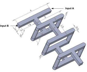
The SAR technique is utilized in the construction of a novel 3D passive micromixer called ‘(Y-U)H’ as shown in Figure 1. One 'Y' and one 'U' segment make up one element and four identical elements constitute the ‘(Y-U)H’ mixer. The cylindrical segments at the inlets and outlets have respective radii of 0.4 mm and 0.6 mm respectively.
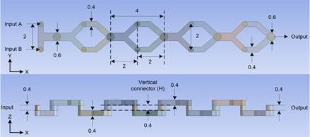
As represented in Figure 1, a vertical cylindrical connection (H) connects each element and each ‘Y’ and ‘U’ segment. The cylindrical connection (H) has a length that ranges from 0 mm to 0.8 mm, rising by 0.2 mm every step. Thus, (Y-U)0 mm (H = 0 mm), (Y-U)0.2 mm (H = 0.2 mm), (Y-U)0.4 mm (H = 0.4 mm), (Y-U)0.6 mm (H = 0.6 mm) and (Y-U)0.8 mm (H = 0.8 mm) represent five ‘(Y-U)H’ mixers with various vertical connection heights.
M. Nimafar et al. [26] have constructed and experimentally investigated the efficiency of the 'H' mixer for Reynolds numbers from to . A newly designed H mixer is represented in Figure 2, the 'H' micromixer geometry is composed of two components: the straight channel and the H-segment, which denotes a single element. One element's length is 1.4 mm, while both inputs and outputs have widths and heights of 0.4 mm. The ‘H’ mixer has a total axial length of 20 mm and is made up of 12 identical elements (only 3 elements are shown below in Figure 2).
3. Numerical Method
Ansys FLUENT 15 uses the finite volume approach to study the mixer's flow characteristics and mixing performance. The mixed fluid leaves the mixer through the output after entering from two inputs. Both fluids in this investigation are assumed to have the physical characteristics of water. The density, viscosity, and diffusions constant of the water is , 1000 kg/m3 and 1×10⁻⁹ m2/s, respectively. The following equation is used to determine the Reynolds numbers, which are a crucial quantity for fluid flow [27].

Where ρ is the fluid density, μ is the dynamic viscosity, and v is the fluid velocity, evaluated at the rectangular channel. The characteristics length d equals 0.4 mm, which is the minimum dimension of the mixers.
An incompressible, laminar, Newtonian liquid in microchannels was taken into consideration. To discretize continuity, Navier-Stokes, and species convection-diffusion equations, Ansys FLUENT 15 used a coupled solver and finite volume approach [21], [28].


Where P is equal to pressure, C is the mass concentration of the species, D is the coefficient of diffusion, and V is the fluid velocity vector. Additionally, ρ is the fluid density and μ is the fluid's dynamic viscosity. The diffusion constant used in this study is 1×10⁻⁹m2/s which is a typical value for water-water mixing [13]. When the mass fraction of the two species reached 0.5, homogeneous mixing was accomplished. The mass concentration of the two species was set at 0 in Input A and 1 in Input B, respectively. No-slip boundary conditions were taken into consideration, and the inputs and output were configured as velocity inlet and pressure outlet, respectively. The implicit SIMPLEC method was utilized to integrate discrete equations linked in the pressure-velocity formulation.
The following formulas are used to determine the mixing performance, which serves as a common benchmark for assessing the mixing process [29] [30].
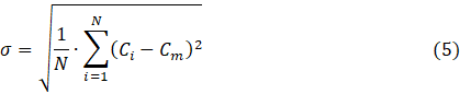
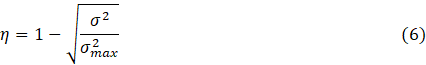
Equations (5) and (6) use the following notation: σ stands for the mass fraction standard deviation at a cross-sectional plane; N is the number of data points in that cross-sectional plane; Ci is the mass fraction at a given point; Cm is the optimal mass fraction; σmax is the maximum variance of the mass fraction over the data range; and η is the mixing efficiency, which swings between zero and one. For applications involving mixing processes, an efficiency of 80% to 100% is appropriate; zero denotes unmixed species and one indicates perfectly mixed species.
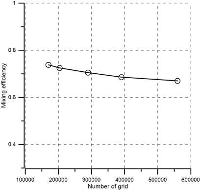
A high-quality mesh model is essential for accurate numerical results [31]. To make sure that numerical data are independent of grid size and shape, it is crucial to perform the mesh independence test [32]. Therefore, structured tetrahedral cells were employed for the numerical test [33]. A path-conforming technique was used to create tetrahedral grid networks without any suppression. For mixer (Y-U)0.6 mm (H = 0.6 mm), six distinct grid systems with a range of nodes from 1.7×10⁵ to 5.6×10⁵ were investigated. Figure 3 displays the mixing efficiency for various grid numbers and there is a small variation in efficiency by increasing the number of grids at . For the simulation, a grid system with 2.90×10⁵ nodes were used in order to minimize the computational expense and time. For the remaining four (Y-U)H mixers, a grid dependency test was also conducted, and nodes of 2.72×10⁵, 2.76×10⁵, 2.98×10⁵, and 2.94×10⁵ were selected for (Y-U)0 mm, (Y-U)0.2 mm, (Y-U)0.4 mm and (Y-U)0.8 mm mixers, respectively.
4. Result and Discussion
A SAR "H" mixer [26] was created, and numerical simulations for 0.083≤Re≤4.166 were run in order to validate the numerical approach. Figure 4 illustrates a comparison between the numerical data of present study and published experimental data for the H mixer after 20 mm along axial length. The agreement between experimental data and numerical simulation findings is good, with less than a 10% deviation.
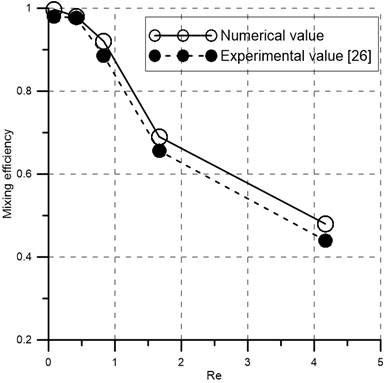
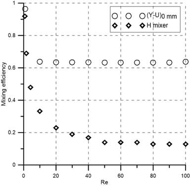
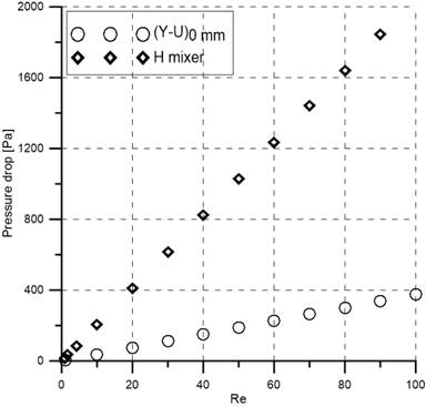
Figure 5 shows the comparison of pressure drop and numerical mixing efficiency between the (Y-U)0 mm mixer and the H mixer. It is clear that, for all Reynolds numbers considered, the (Y-U)0 mm mixer not only has better efficiency but also a smaller pressure drop than the H mixer. At , the (Y-U)0 mm mixer produces five times less pressure drop (400 Pa), and three times higher efficiency (64%) compared to the H mixer. It follows that, for all Reynolds values considered, the suggested (Y-U)0 mm mixer outperforms the H mixer. As a result, only (Y-U)H mixers were examined in further detail.
The overall mixing performance of all mixers with different vertical connector height H (0 mm to 0.8 mm) was analyzed. Figure 6 displays the water mass fraction inside the mixers at Reynolds numbers equal to 1 and 50. At Re=50 there is a large fluctuation in the water mass fraction for every mixer. Water concentration changes noticeably as Reynolds numbers rise from 1 to 50, indicating that efficiency would decline at high Reynolds numbers (Re=50) in comparison to low Re (Re=1).
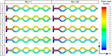
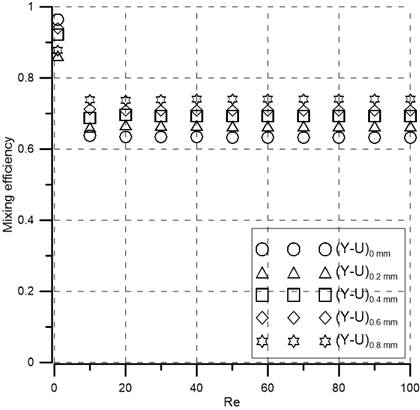
Figure 7 shows the variation curves of mixing efficiency (η) for (Y-U)H micromixers changing the vertical cylindrical connecting height (H) under different Reynolds numbers. It can be found that all mixers show the same trend at Reynolds numbers ranging from 1 to 100. At low Reynolds numbers , the liquid flows at a low speed in the channel, and the mixing mechanism is mainly diffusion. Hence good mixing is achieved due to longer residence time, which is about 90% for all mixers. As the (Re=1) value increases, the flow rate in the mixer increases, and the time for the diffusion of chemical molecules decreases, resulting in a decrease in the mixing efficiency. When (Re≥10), the mixing index do not changes with the increase of , influence of the secondary flow is not strong enough to compensate for the shorter mixing time due to the increase in flow rate (as shown in Figure 8). It is clear that mixing efficiency depends positively on vertical connector height (H). Efficiency increases with the increase of H because of extra path length which in turn gives additional mixing time. All mixers exceed 60% efficiency at higher Reynolds numbers (10≤Re≤100). Moreover, (Y-U)0.8 mm yields the highest efficiency (74%) for 10≤Re≤100.
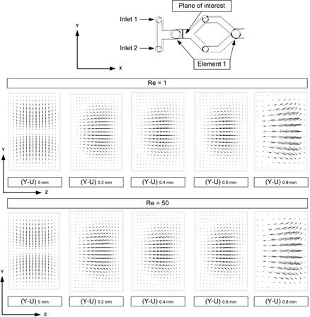
Figure 8 depicts the velocity vector plots on the YZ-plane for five mixer channels at Re=1 and Re=50. The flow pattern is almost the same in every cross-section, and the secondary flow is negligible. But the efficiency is good because at low Reynolds numbers (Re=1) fluids have more time to mix. At a Reynolds number of 50, the secondary flow increases for all mixers but not at a significant level. Hence the efficiency decreases at high Reynolds numbers (10≤Re≤100).
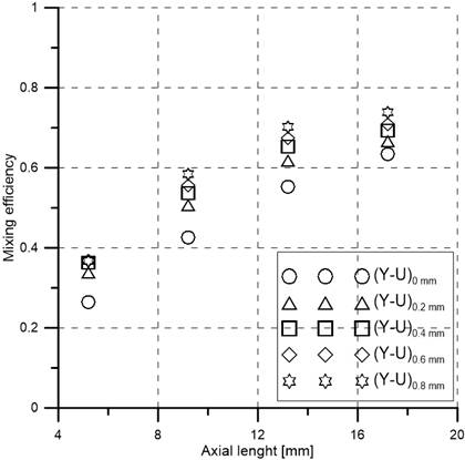
The relationship between mixing efficiency and axial length at Re=30 is presented in Figure 9. The curves follow the same trend and efficiency increases with the axial length, as expected. The (Y-U)0 mm mixer shows the lowest efficiency, and the (Y-U)0.8 mm mixer shows the highest efficiency (74%) at the output due to its longer fluid path. An efficiency of more than 95% can be reached by adding more elements which will increase the total fluid path.
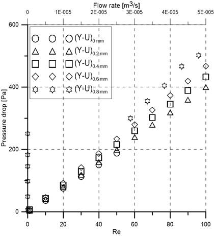
Figure 10 expresses the relationship between pressure drop, flow rate, and Reynolds numbers varying from 1 to 100. Pressure drops increase with the increase of Reynolds numbers (and flow rate) for all mixers. It is evident that vertical cylindrical connecting height (H) affects the pressure drop; pressure drop increases with the increase of vertical cylindrical connecting height (H). The (Y-U)0.8 (H = 0.8 mm) mixer has the highest pressure drop due to its longest channel length.
6. Conclusion
The design and investigation of the performance of novel SAR (Y-U)H mixers are the main purposes of this work. A (Y-U)H mixer is made up of four identical elements. The vertical connecting cylindrical length (H) of the mixer is changed from 0 mm to 0.8 mm by 0.2 mm each time to observe the impact on the mixing index. Using Ansys FLUENT 15 mixing performance is estimated numerically changing Reynolds numbers (1≤Re≤100). Additionally, a well-known SAR ‘H’ mixer is examined, and the numerical data is computed and compared with published experimental data. At all investigated Reynolds numbers, the suggested (Y-U)H mixers perform better than the existing H mixer. The (Y-U)0.8 mm mixer offers the best mixing efficiency (74%) compared to all proposed mixers. Since secondary flow is not strongly present in the mixers, increasing Reynolds numbers does not result in an improvement in mixing efficiency. However, because the fluids have adequate time to mix, efficiency is high (90%) for low Reynolds numbers (Re=1). Therefore, the (Y-U)H mixers have potential applications at low Reynolds numbers.
References
[1] D. Wang, D. Ba, K. Liu, M. Hao, Y. Gao, Z. Wu and Q. Mei, "A Numerical Research of Herringbone Passive Mixer at Low Reynold Number Regime," Micromachines, vol. 8, pp. 325, 2017. doi: 10.3390/mi8110325 View Article
[2] V. Khaydarov, E. S. Borovinskaya and W. Reschetilowski, "Numerical and Experimental Investigations of a Micromixer with Chicane Mixing Geometry," Appl. Sci. vol. 8, pp. 2458, 2018. doi.org/10.3390/app8122458 View Article
[3] C. Y. Lee, W. T. Wang, C. C. Liu and L. M. Fu, "Passive mixers in microfluidic systems: A review," Chemical Engineering Journal, vol. 288. pp. 146-160, 2016. doi: 10.1016/j.cej.2015.10.122 View Article
[4] S. Rampalli, T. M. Dundi, S. Chandrasekhar, V. R. K. Raju and V. P. Chandramohan, "Numerical Evaluation of Liquid Mixing in a Serpentine Square Convergent-divergent Passive Micromixer," Chem. Prod. Process Model., vol. 15, no. 2, pp. 1-11, 20203 doi: 10.1515/cppm-2019-0071 View Article
[5] G. Cai, L. Xue, H. Zhang and J. Lin, "A review on micromixers," Micromachines, vol. 8, no. 9, 2017. doi: 10.3390/mi8090274 View Article
[6] A. Enders, I. G. Siller, K. Urmann, M. R. Hoffmann and J. Bahnemann, "3D Printed Microfluidic Mixers-A Comparative Study on Mixing Unit Performances," Small, vol. 15, no. 2, 2019. doi: 10.1002/smll.201804326 View Article
[7] N. T. Nguyen and Z. Wu, "Micromixers - A review," Journal of Micromechanics and Microengineering, vol. 15, no. 2. 2005. doi: 10.1088/0960-1317/15/2/R01 View Article
[8] M. Guo, X. Hu, F. Yang, S. Jiao, Y. Wang, H. Zhao, G. Luo and H. YuM, "Mixing Performance and Application of a Three-Dimensional Serpentine Microchannel Reactor with a Periodic Vortex-Inducing Structure," Ind. Eng. Chem. Res., vol. 58, no. 29, pp. 13357-13365, 2019. doi: 10.1021/acs.iecr.9b01573 View Article
[9] M. R. Mahmud, S. Hossain and J. H. Kim, "A SAR Micromixer for Water-Water Mixing: Design, Optimization, and Analysis," Process, vol. 9, pp. 1926, 2021. doi: 10.3390/PR9111926 View Article
[10] V. Khaydarov, E. S. Borovinskaya, and W. Reschetilowski, "Numerical and experimental investigations of a micromixer with chicane mixing geometry," Appl. Sci., vol. 8, no. 12, pp. 3-6, 2018. doi: 10.3390/app8122458 View Article
[11] A. Usefian and M. Bayareh, "Numerical and experimental investigation of an efficient convergent-divergent micromixer," Meccanica, vol. 55, no. 5, pp. 1025-1035, 2020. doi: 10.1007/s11012-020-01142-0 View Article
[12] M. Juraeva and D. J. Kang, "Mixing performance of a cross-channel split-and-recombine micro-mixer combined with mixing cell," Micromachines, vol. 11, no. 7, 2020. doi: 10.3390/mi11070685 View Article
[13] V. Viktorov, M. R. Mahmud, and C. Visconte, "Design and characterization of a new H-C passive micromixer up to Reynolds number 100," Chem. Eng. Res. Des., vol. 108, pp. 152-163, 2016. doi: 10.1016/j.cherd.2015.12.005 View Article
[14] V. Viktorov and M. Nimafar, "A novel generation of 3D SAR-based passive micromixer: Efficient mixing and low-pressure drop at a low Reynolds number," J. Micromechanics Microengineering, vol. 23, no. 5, 2013. doi: 10.1088/0960-1317/23/5/055023 View Article
[15] V. Viktorov, C. Visconte, and M. R. Mahmud, "Analysis of a Novel Y-Y Micromixer for Mixing at a Wide Range of Reynolds Numbers," J. Fluids Eng. Trans., vol. 138, no. 9, pp. 1-9, 2016. doi: 10.1115/1.4033113 View Article
[16] M. A. Ansari, K. Y. Kim, K. Anwar, and S. M. Kim, "A novel passive micromixer based on unbalanced splits and collisions of fluid streams," J. Micromechanics Microengineering, vol. 20, no. 5, 2010. doi: 10.1088/0960-1317/20/5/055007 View Article
[17] S. Hossain and K. Y. Kim, "Mixing analysis of passive micromixer with unbalanced three-split rhombic sub-channels," Micromachines, vol. 5, no. 4, pp. 913-928, 2014. doi: 10.3390/mi5040913. View Article
[18] W. Raza and K. Y. Kim, "Asymmetrical split-and-recombine micromixer with baffles," Micromachines, vol. 10, no. 12, 2019. doi: 10.3390/mi10120844 View Article
[19] S. W. Lee and S. S. Lee, "Rotation effect in split and recombination micromixing," Sensors Actuators, B Chem., vol. 129, no. 1, pp. 364-371, 2008. doi: 10.1016/j.snb.2007.08.038 View Article
[20] M. R. Mahmud, "Numerical Analysis of a Planar O Micromixer with Obstacles," J. Eng. Adv., vol. 3, no 2, pp 64-71, 2022. doi.org/10.38032/jea.2022.02.004 View Article
[21] T. S. Sheu, S. J. Chen and J. J. Chen, "Mixing of a split and recombine micromixer with tapered curved microchannels," Chem. Eng. Sci., vol. 71, pp. 321-332, 2012. doi: 10.1016/j.ces.2011.12.042 View Article
[22] G. Xia, J. Li, X. Tian and M. Zhou, "Analysis of flow and mixing characteristics of planar asymmetric split-and-recombine (P-SAR) micromixers with fan-shaped cavities," Ind. Eng. Chem. Res., vol. 51, no. 22, pp. 7816-7827, 2012. doi: 10.1021/ie2026234 View Article
[23] S. Hardt, H. Pennemann, and F. Schönfeld, "Theoretical and experimental characterization of a low-Reynolds number split-and-recombine mixer," Microfluid. Nanofluidics, vol. 2, no. 3, pp. 237-248, 2006. doi: 10.1007/s10404-005-0071-6 View Article
[24] D. S. Kim, S. H. Lee, T. H. Kwon and C. H. Ahn, "A serpentine laminating micromixer combining splitting/recombination and advection," Lab Chip, vol. 5, no. 7, pp. 739-747, 2005. doi: 10.1039/b418314b View Article
[25] G. Orsi, M. Roudgar, E. Brunazzi, C. Galletti and R. Mauri, "Water-ethanol mixing in T-shaped microdevices," Chem. Eng. Sci., vol. 95, pp. 174-183, 2013. doi: 10.1016/j.ces.2013.03.015 View Article
[26] M. Nimafar, V. Viktorov and M. Martinelli, "Experimental comparative mixing performance of passive micromixers with H-shaped sub-channels," Chem. Eng. Sci., vol. 76, pp. 37-44, 2012. doi: 10.1016/j.ces.2012.03.036. View Article
[27] M. Nimafar, V. Viktorov and M. Martinelli, "Experimental Investigation of Split and Recombination Micromixer in Confront with Basic T- and O- type Micromixers," International Journal of Mechanics and Applications, vol. 2, no. 5, pp. 61-69, 2012. DOI: 10.5923/j.mechanics.20120205.02 View Article
[28] J. M. Park, D. S. Kim, T. G. Kang and T. H. Kwon, "Improved serpentine laminating micromixer with enhanced local advection," Microfluid. Nanofluidics, vol. 4, no. 6, pp. 513-523, 2008. doi: 10.1007/s10404-007-0208-x View Article
[29] W. Raza, S. Hossain and K. Y. Kim, "A review of passive micromixers with a comparative analysis," Micromachines, vol. 11, no. 5, 2020. doi: 10.3390/MI11050455 View Article
[30] M. R. Mahmud, "Numerical Investigation of Liquid-Liquid Mixing in Modified T Mixer with 3D Obstacles," J. Eng. Adv., vol. 2, no. 2, pp 87-94, 2021. doi.org/10.38032/jea.2021.02.004 View Article
[31] C. K. Chung and T. R. Shih, "A rhombic micromixer with asymmetrical flow for enhancing mixing," J. Micromechanics Microengineering, vol. 17, no. 12, pp. 2495-2504, 2007. doi: 10.1088/0960-1317/17/12/016 View Article
[32] X. Shi, L. Wang, S. Huang and F. Li, "A novel passive micromixer with an array of Koch fractal obstacles in a microchannel," J. Dispers. Sci. Technol., vol. 42, no. 2, pp. 236-247, 2021. doi: 10.1080/01932691.2019.1674156 View Article
[33] T. Dehghani, F. Sadegh Moghanlou, M. Vajdi, M. Shahedi Asl, M. Shokouhimehr and M. Mohammadi, “Mixing enhancement through a micromixer using topology optimization,” Chem. Eng. Res. Des., vol. 161, pp. 187–196, 2020. doi: 10.1016/j.cherd.2020.07.008 View Article